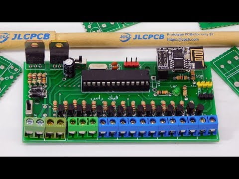
In the name of of Allah the Merciful And peace and blessings be upon our master Muhammad peace be up on him Welcome all Mohamed Ahmed from the channel Vick Ras In today's video The method of assembling the Smart House PCB (PCB) panel will be illustrated Start with the PCB design at the bottom of the video Through the electronic parts used And the way they are assembled with a simplified explanation Do not forget to share the video with your friends To contribute to the dissemination of interest We first remind you of the way to buy from JLCPCB You register on the site Then press QUOTE NOW Then click Add your gerber file Then we add the Gerber file to our design Then wait until the file is raised Then you will see an illustration of the design So you can review it before completing the application Then press SAVE TO CART Once you have completed your order, click Checkout securely Then add your shipping data Then select the appropriate payment method Until you arrive at the earliest Insha'Allah On the blessing of God we begin These are the three designs (PCB) we will work on in today's lesson and the next lessons Designed for Smart Farm and Smart House II Then the new design of the reels You get the boards (PCB) in this way They are 10 plates (PCB) 10 in 10 cm I have opened it before and Preparation one for clarification on it Each panel is a two-circuit (PCB) that you can easily disconnect As you can see the paintings are of high quality We can install all components on them You can use sharp knife to facilitate the separation process Easily By the holes shown Such as what we have explained in previous lessons on the program (Fritzing) And how to use them To separate designs To save wasted space In the tablet (PCB) This is the PCB design that will be pulled down the video A brief description of the components used First ATMEGA 328 Which consists of 28 parties each 14 of them in the direction Like what is shown before you And with its crestal 16mhz Two 22pf capacitors Here the ESP8266-01 All sides are fully connected Which has been highlighted in more than one previous video Specifically in the PCB design of the Smart Agriculture Department Here is the circle of current regulation Which depends on the LM317T With suitable resistors for output of 3.3 volts and also 5 volts These are the resistors shown to regulate current With LM317T Then Circuit protection of the plate of reverse positive and negative polarity Adopted on two diodes 2 amp Then key to disconnect the circuit and turn it on Fuse or epoxy 1 amp for protection Here is the tendency to enter positive and negative current Such as illustrated Then here 15 resistance 1 kilo ohm Below are 15 transistors 2n2222 Then a rosette to assemble the terminals of the positive And another trilogy to use for example For RGB or as three other keys And 6 other rosettes To complete 15 keys with us Here you can install Servo motor, Connector-tip terminal (PWM D3) With its negative and positive parties Then the tip (D2) was used to install it heat sensitive and moisture (DHT22) Or we can use it to connect the water level sensor (DigitalRead) To maintain the water level inside the water tank So we have used both parties (D2-D3) For temperature sensor and humidity level Servo motor To lock and secure doors from inside Here is the party of the (A0) Will be used to connect external keys As explained in the lesson of running 7 keys on one end of the analog We will use it here to operate 15 keys If we can not do that We can use any other analog party By eliminating resistance, transistor and direct conduction For example Here the party number (A1) Connector on the resistor then the transistor You did not install them and then we plug (A1) the direct plug shaft So we have another analog party on 14 keys Here is a lamp (LED) to clarify the situation Here, too, resistance of 10 kW for the RES key, If you wish Then we go to the assembly This is used to remove and install IC ATMEGA328 And the other we use to connect Wi-Fi (ESP8266-01) It is about 8 limbs Then we install the (Crystal16mhz) Then two 22pf capacitor Then we bend the wire from the other direction for installation We can control the painting better The components do not drop from the PCB board.
Then we start to install resistors 1 kilo ohm And 15 resistance Of course, organization and arrangement is very important at this stage So you can weld the sides Because of the parties And if we cut the limbs will consume you longer Then we start to install the resistors assigned to the current circuit You should pay attention here to the type of each resistance The first of the left 1.5 kilo om Then 510 ohm resistance For the 5 volt circuit Then 510 ohm resistance Then 330 ohm Of 3.3 volts Then we install the condenser Its positive and negative terminals are shown on the board Then we install the diode In the same way as shown on the board Then we start to weld the sides This is explained to encourage viewers Who have never used a welding iron Try it Then we cut the length on the sides after the end of the welding process So that we can deliver the iron to the other parties We complete the welding of the terminals (ATMEGA328) They are 28 parties, as we explained earlier In each direction 14 parties This way to illustrate the ease of welding The most important thing to use a good type of iron And the temperature is appropriate no less and no more Because of poor electricity during video filming The temperature of the kettle was inappropriate For welding only small parties That's why I did not record some shots so I do not prolong the video And waste your time in this Then we complete the welding of the 15 resistors Such as illustrated As you zoom in closer to show you all the details Then we cut the parties using a wire cutter Then we complete We repeat the cutting of the limbs At this stage it is this way You can check the resistors value through the colors shown Then complete the installation of the (LED) The positive and negative terminals will be explained in your design Then complete the remaining resistors according to the value shown on the board For example, resist 2 kilo ohms and 1 kilo ohm connect to Wi-Fi (ESP8266-01) This is also a resistance of 10 kilos to the RES switch.
Then we complete the welding process in this way Such as the presence of wire prevents the iron from reaching well to other places Then complete the welding of the ends of the keys Switching switch, servo motor, and another servo motor switch To connect 5 volts of regulator or volt to full input As per 12, 9 or 7 volts Or depending on the type of additive used Then we install the remaining 15 transistors 2n2222 It is a very suitable type for such projects With a capacity of 400 mA You can carry Rilah without any problems Then we complete the welding parties You did not fully explain them for non-repetition This is the form that has been reached at this stage The remaining is very few They are the three extensions Connected to (A0, D2, D3) You can use them to connect servo and heat and humidity sensor And the symmetric end of the keys Then we complete Install the batteries to connect It is advisable to use different colors Such as what is clearly the effect of weak voltage on the temperature of the iron Affects the welding process I can not explain it but it is very simple Therefore, the importance of the temperature of the iron should be noted For easy connection of such limbs with ease The ESP is installed.

Then ATMEGA328 This way I can program it more than once for ease of jaw and installation We will explain how to use this painting in two ways Such as Alexa, RemoteXY You can also turn off the video here to check every plug So you can do it easily We stayed in the fountain or the fuse So far I have not been able to get the Fuse (SMD) I made up for it with a fine brass wire To replace instead of the fuse To melt in the event of a problem or reversal of electrodes We connect electricity In the name of God As described works excellently After connecting the power supply, you must check important points Such as note any high temperature electronic cutting Before connecting, make sure the direction of the mark is in the ATMEGA.
Be in the same direction as the RES (ESP) Do not forget to check the heat of the organizations together as they are a quick guide to having a problem Then we try Local network programming For clarification Reading the heat and humidity sensor is not correct The DHT22 works well I can not identify the problem in the library or the DHT11 now I did not use it here because I only have one piece installed in another design Like everything shown is working well The response speed is also high due to working on the LAN In the next lesson we will explain the programming method with the program (RemoteXY) And how to write code and modify it And additions that have been used with us So we've reached the end of today's video I hope that God has been successful in delivering information If you like the video, do not forget to invite me to click on like It subscribes to the channel and activates the alarm bell To receive a new notice And do not forget to share video among your friends Peace, mercy and blessings of God
As an Amazon Associate I earn from qualifying purchases.


