
As an Amazon Associate I earn from qualifying purchases.

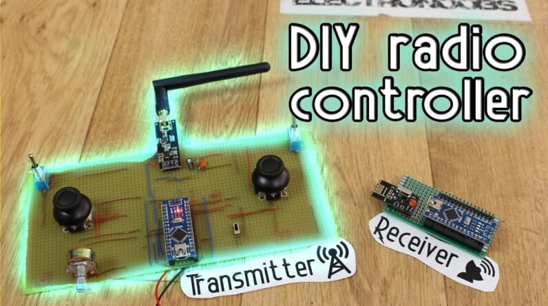
what's up my friends welcome back so let me explain today's project you see I've already made a lot of projects that use this on RF 24 ad module and I've already built a lot of Arduino based radio control as you can see here but I never explained only how to build the radio controller because it was always part from a bigger project as my Arduino based drone the radio tank here or the Spitfire plane so a lot of you guys had some problems establishing the connection between the two modules or understanding the code so today I'll make a tutorial on only how to build the radio controller so this project will have two parts first we'll build the transmitter and then the receiver which will be as any other commercial receiver with some PWM outputs I haven't tested the range of this project yet but I did with my other projects which are more than the same and I had a good signal up to 700 meters well guys before we start I would like to ask you to visit my Q&A page but not only to post a question but also to help others out you see I don't have time to answer all of your questions and sometimes I don't know the answer so please join the community and help others out the link is down below also guys I really appreciate if you support my projects on my patreon page usually I post my videos there one day earlier and also my design parts all my schematics and so on so please visit my patreon page I really appreciate that guys so let's begin this project let's see how to establish the connection between the transmitter and receiver how these little modules designer Estonia for module works and so on so let's get started [Music] this project is brought to you by jl CPCB which is a manufacturer of quick PCB prototypes for more than 10 years and is the site that i use for all of my PCBs once design applaud your Gerber files on the GLC PCB site get a full review of the PCB select your desired settings and order the PCB for amazing prices i've ordered ten of my prototype PCBs for only $2 and receive those in six days crazy right so order your quality PCB and make your projects look a lot more professional what's up my friends welcome back here I have my a t10 radio controller it has 12 channels and is compatible with both these two receivers one has a PWM and SBUs signals and the other one has PWM as pass but also ppm and that's exactly what we will build today we will build the radio transmitter and then talk about two types of receivers P mm and PP n signal so let's begin so first let's build the transmitter because it will be the same for both type of receivers in one of my past tutorials have used an old already made radio controller and hack it with an Arduino inside but in order to not confuse you guys too much I will build today's project using simple separated parts here is what we need first a big drill PCB to solder everything on it I want two joysticks each with two channels so I will use this small joysticks that I've bought from eBay for very cheap I want my controller to have two more channels and I will make those digital channels so I will use this toggle switches that will send a 0 or 1 finally I add an extra analog channel using a normal potentiometer of course we'll need the an RF 2 info radio module for the transmitter you should use a power amplified one so we will have more range you see the transmitter needs a powerful radio module but the receiver should work ok with the normal one as well if the signal gets to it it should work just fine of course you could use power amplified radio modules for both the transmitter and receiver but that would increase the price a bit now a very important part of this project it's a good voltage regulator you see the Arduino works at 5 volts but the an RF 24 module at 3.3 if we supply 5 volts to the radio module we will burn it so I will use the Arduino Nano which already has a triple tree volts output but is not powerful enough it can supply enough current for that I will use the AMS 1 1 1 7 3.3 volts voltage regulator finally to supply the circuit we could use a lipo battery or maybe directly a net volts battery like this one but it won't last as much as the lipo check the part list below to see all the extra small components this is the schematic of the radio transmitter have it in front of you while soldering and make sure you follow well all the connections I take the piece of true PCB and a first holder in place the joysticks they have these thick metal pins so you would probably have to enlarge four holes for each one in order to fit them in next I soldered the radio transmitter module in the top center position of the board so it won't have too much interference now a very important step is to solder the Arduino quite close to the radio module you see the longer are the wires or the PCB connections from the Arduino to the module the higher the noise will be so make sure you have very short connections and if you use free wires to connect the SP pins you could also please ground around mozi and mine so wires in order to lower the noise a bit that helped me in certain situations next I add the two toggle switches one on each side and those will be the two digital channels and finally the extra potassium meter that will be an analog channel to power on and off the board I've added this kind of sliding switch the battery will be connected to the switch so when we slide it the entire board we'll be supplied finally I soldered the triple tree voltage regulator with the coupling capacitors and make all the connections as in the schematic those connections include supplied 5 volts and ground to the joysticks to the switches and the potentiometer connect 3.3 volts to the an RF 24 module make the SP connection by soldering the Clarke mozi and missile but also chip select and chip enabled and finally solder each analog output from the joystick potentiometers remember to solder the wires from the battery to the sliding switch also very important make sure that all the voltages are correct you should have exactly 3.3 volts for the radio module and 5 volts to the Arduino now the board is ready all these there to do is to program it if you want a better looking board feel free to download my design from below of this board you have the Gerber files in a zip below just download it and send it to GLC PCB and order your board for a very low price and give your project this professional look and also with a gyro control so you could move the radio control device just by moving the controller check the description for more well we have the transmitter now let's build a receiver that should be quite easy all we need is the Arduino Nano the an RF 24 receiver like this one another trip one trip voltage regulator and a small PCB we will use this command in the description you will see two schematics for the receiver they are more than the same but one has seven PWM outputs and the other one only 1 ppm output on digital pin 2 depending on the project that you want use one or another ok so i've sold her everything in place the arduino with female pin so i could take it out when i want the radio module and make the connection just as in the schematic i soldered the AMS strip on three voltage regulator and remember to add a 10 micro farad and 100 nano farad capacitor to smooth the trip on three voltage the receiver won't need a battery supply since just as any other commercial receiver it we'll be supplied with directly 5 volts as you could see here on this receiver we have ground 5 volts and signal now as you can see this commercial receiver has 90 degrees pins for each channel I don't have that now so I will use normal straight PCB pins you have to solder three pins for each channel ground five volts and signal this kind of radio connection could have up to 32 channels which is the maximum supported by the other half Tony 4 module but the Arduino doesn't have that much digital pins in my case I only have 7 channels now we are ready to program both the transmitter and receiver this is the part where most of you guys had some problems since you weren't able to receive data so for that before let's make a quick test to keep it simple on the breadboard connect the transmitter and the Arduino with only one potentiometer connected to analog pin a zero use this example schematic for that make sure that the aspect connection is as in the schematic you could also one ground around mozi and missile wires for last noise also add a small capacitor between ground and tripping tree votes now on another breadboard make the same configuration but in this case without the potentiometer since this will be the receiver now download the transmitter and receiver test calls from below make sure they are the test codes not the final code of the project now open arduino ide two times and open the transmitter code in one and the receiver in the other upload the codes and then go to the serial monitor of the receiver part and open it set the bout rate to 9600 and you should see the data for channel 1 move the potentiometer and the data should change according to the potentiometer if there is no good connection the data will always be the same even if you move the potentiometer if you receive data then your connection is working so guys we can program our radio controller now download the transmitter receiver codes be careful there are two receiver codes one for PWM and the other for ppm I will use PWM for now this is the transmitter code let me explain it step by step first we import the libraries that we need make sure you have the an RF 24 library installed if not you could download it from below then go to sketch include library and add that zip library and select the zip file that you have just downloaded and now we are good to go you could also use the library manager to install it next we define the radio pipe this code should be the same in the transmitter and receiver since it is a unique code for the radio connection having multiple receivers with the same pipe code they will all receive the same data from the transmitter next we define the chip select and chip enabled pins for the SP communication these two could be any digital pin of the arduino in my case our pin 9 and 10 the other SP panes must be digital pin 11 12 and 13 since those are the clock mozi and missile ports of the arduino and they can be other pins now we create a structure type variable and store each channel value in this structure this could have up to 32 channels each of eight bits or better said one byte I name each channel from channel 1 to 7 now we create a variable with that structure and name it send data and this will be the package that we will send ok in the setup void we begin the radio communication using the begin function that the an array of 24 library already has we set the radio communication configuration and open the radio pipe with the variable my radio pipe defined before the next lines will reset the channel values in this case all 4 potentiometers of the joysticks will be in the middle position since we can always send 8 bits per channel which in decimal is 255 well the middle of 255 will be 107 that's why I reset channel to fall with these values next we have two digital channels channel 5 and 6 with value 0 or 1 and finally another analog channel but with value 0 since this will be connected to a potentiometer that will have its initial position to zero in the void loop we have to read each analog and digital inputs which in this case are analog pins a 0 to a 4 and digital pins D 2 and D 3 we map these values to range between 0 and 255 since we can only send a bit and store the values in our send data variable and we send the entire instruction using the radio that write function okay so the transmitter code was very simple now let's take a look on the receiver side it is a bit longer but that's because each line is repeating for each channel once again import the needed libraries in this case we import servo library as well for the PWM signals define the pipe as in the transmitter code and the chip select and enable pins again we create seven by structure for the received values now we create seven server types and define the PWM emission value for each channel in the setup loop we attach the PTM signals to pins from digital D 2 to D 8 and finally we configure the radio connection and start listening next we have this function called receive data this function will receive the data and store it in our structure now in the word loop we use this receive data and get the values right below we map the received values from eight beats to a value from 1,000 to 2,000 microseconds since those are usually developed at any commercial radio receiver used for PWM signal using the right microsecond function we create each of the seven p mm signals and we are done now connect the USB and a put these codes to the transmitter and receiver I connect the battery to the transmitter and pour it on supply 5 volts to the receiver with the USB and I will connect two of these channels to my oscilloscope and there you go i perfectly receive the data from the transmitter if the values are not exactly in the correct range which is from 1,000 to 2,000 microseconds then go to the receiver code and change these values here in order to match the minimum and maximum values for each Channel so there you go my friends we have built our own radio control that works exactly as any other commercial one but for way less money in the description you also have the code and schematic for a ppm receiver that will create an 8 channel ppm signal on digital pin to the rest of the project is the same we have two digital channels with switches for channel for logistics and one extra potentiometer for channel 7 what is left to do is probably 3d printer case for this project or maybe leave it like this so it should have a more DIY look remember that below you have the Gerber files for this transmitter board if you want to send it to Jessie PCB and print it this board has 4 analog channels with these blue joysticks and two more digital channels with some sliding switches here you could also add a gyro module and send that data and control the air see machines only by moving the controller but that is for a future project so stay tuned well guys you have all the codes and schematics below in the video description and also my patreon page check my web page electronics comm for more details and if you would like to support me check my patreon page as well I would really appreciate that guys it will help me a lot and I will have more and more awesome projects I hope that you enjoyed this video if so don't forget to click the like button like crazy and share this video with your friends if you have any question about this video or any other just leave it in the comment section below or my Q&A page also don't forget to subscribe and watch all of my other way tutorials and remember if you consider helping my projects check my patreon page as well thanks again and see you later guys [Music]
As an Amazon Associate I earn from qualifying purchases.