

As an Amazon Associate I earn from qualifying purchases.

The room thermometer and Bluetooth speaker
are two, standalone DIY projects we have currently built and we will be building more in the
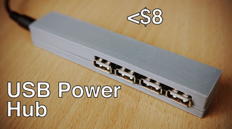
coming videos. Powering all these projects is going to an issue and in this video, we
will learn how to build a very simple USB power hub to power your DIY projects. When designing a power related project, there
are two main things you need to worry about – the voltage and the current. Since this
is going to be a USB power hub, the voltage will be 5V and the current should at least
be in the 2-3A range so that it can safely provide power to multiple devices at the same
time. I would like to make the input voltage a little flexible so that we can power it
through different sources, depending on what’s available.
I have a spare 12V, 5A power supply
that I will be using to power this. In order to convert this 12V input to 5 volts,
we need a voltage regulator and the first one you might think off is this 7805 that
is easy to use and very compact. However, it is a linear regulator and like all linear
regulators, it is inefficient. At a very basic level here’s how they work. They have a
sense network that can determine the input voltage and they then drop the excess voltage
by using something called a pass element and this generates heat. The amount of heat generated
depends on the output voltage as well as current being drawn. Let’s take our example here. If we supply
the 7805 with a 12V input, it will provide a 5V output.
If we do not draw any current
from the output then they will be virtually no heat generated. If we draw current of around
100mA, then there will be some heat generated and this will be noticeable after some time.
Also, if we increase the current drawn to about 500mA then there will be much higher
heat generated. You would most likely have to use a heatsink to avoid damaging the voltage
regulator. This means that for a constant input voltage, the heat generated will increase
as the current drawn increases. Conversely, if we draw the same 100mA but
supplying an input voltage of 24V, then the heat generated will be much higher, as the
voltage regulator has to drop the excess voltage. Thus, when constant current is being drawn,
the heat generated will increase as the input voltage increases. The efficiency of these
voltage regulators is around 50% at best and for that reason, we wouldn’t be using one
here as we would like the power supply to handle various input voltages and supply high
current without having to worry too much about heat. A switch mode power supply is another type
of power supply that can be used to either convert a low voltage input to a high voltage
output or to convert a high voltage input to a low voltage output.
If the output voltage
is lower than the input, then it is called a step-down or buck converter. If the output
voltage is higher than the input, then it is called a step-up or boost converter. Switching
voltage regulators are slightly more complicated compared to the linear voltage regulators
but the advantage is that their efficiency is generally around the 90% mark or more,
which means that they do not generate as much heat and can be safely used when higher current
outputs are needed. At a very basic level, switch mode regulators tend to move small
chunks of energy from the input to the output.
They do this by using a switching controller
and a storage element, which is usually an inductor. Switch mode power supplies are used in a lot
of household electronics but thankfully there are various modules available for hobby use
as well. We will be using the LM2596 voltage regulator module that is commonly available.
It can safely handle a maximum input voltage of around 40V and it can supply an output
current of about 3A which is more than what we need. This also means that you can use
pretty much any power adaptor that you may have as long as the voltage is about 9V or
higher.

The modules also have an adjustable trimpot so that you can vary the output voltage
which is perfect. Here’s what you will need for this build.
We have the LM2596 module, a few USB type A breakout boards, and you would also need
a DC jack to connect to the power adaptor. First, let’s solder the DC jack to the input
of the power module. When you switch ON the power supply, the LED on the module should
start glowing, we then connect a multimeter in the DC voltage measuring mode and adjust
the trimpot till the voltage output is about 5V.
Once this is done, you simply need to
wire the output to the individual USB connectors. Before we do this, let’s talk about the
enclosure. I did not find a suitable enclosure that could
be used for this project, so I went ahead and designed a simple one that can house all
the electronics. There’s a link in the description if you’d want to use it. This is how all
the electronics will fit in, so make sure you use the correct wire lengths. Wire up
all the USB ports and then power up the unit to make sure you have 5V across them with
the correct polarity.
Once this is done, it’s time to place the
electronics inside the enclosure. You can start by gluing the USB ports in place, followed
by the power module and then the DC power jack. I rewired the DC jack so that it’s
positive terminal is close to the positive input of the LM2596 module. Make sure you
are happy with the final setup and then use the top half to seal the unit as it has a
lip and groove.
The enclosure should fit together nicely, but this will depend on the quality
of the print, you can add a bit of glue to hold it together. This hub has 4 ports, but you also can buy
these split USB cables that can be used to connect up to 8 devices in total. As you’ve
seen, this only distributes power and it will not work with smart devices like your smartphone
that also make use of the data lines for communication. I would recommend that you only use this to
power your DIY projects. Before we conclude, let’s talk about the
total cost to build this. First, we had the power module, then the 4 USB ports, a DC power
jack and finally, some wire and the enclosure. That’s it for this video. We will continue
building more DIY projects in the coming weeks and several of them will also be USB powered.
If you liked this video, then don’t forget to like, share and subscribe, it helps massively
with the YouTube algorithm.
Thank you for watching and I will see you in the next one..
As an Amazon Associate I earn from qualifying purchases.