
As an Amazon Associate I earn from qualifying purchases.

Hello friends, welcome to TechStudyCell. in
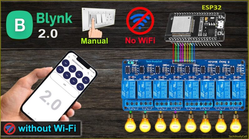
this video I will make an ESP32 home automation project using the new Blynk IoT platform. I have already made a similar project using
ESP8266 NodeMCU, after that, I have received a lot of requests to make the same project
using ESP32 and 8-channel relay module. I will cover that in this video. and I will highly recommend you to was the
complete video as I have shared all the required information for this project during the video. in this project, I am going to use this PCB
but you can also make this project just by using ESP32, an 8-channel relay module and
to control relays manually you can use this type of 2-pin push button or any latched switch. so in the switch, you can see, this is the
common ground and these wires will connect with ESP32 GPIO.
So this is a very simple
connection I have made to use these switches. I will also share the circuit diagram. you need these components to make this project. this is the complete circuit diagram for this
project. here you can see I have given the 5 volt supply
to ESP32 and relay module. If you want to connect any latched switch,
then you can refer to this circuit. here you can see, I have connected the switches
across the GPIO pins of ESP32 and ground.
And this is the 5V control circuit. and you can refer to this circuit to connect
the 220-volt appliances with the relay module. and the control pin of the relay module is
connected with ESP32 GPIO as per this circuit. here you can see there are a lot of connections,
so please make sure there should not be any loose connection if you use jumper wires to
connect ESP32 with the relay module. now to avoid any loose connections I am going
to use this PCB. but as I said, you can also make this project without using any custom
design PCB. still, if you want to get this custom-designed PCB then download the Gerber
file from the video description and order it from the JLCPCB. you can order any custom
design PCB from jlcpcb with three simple steps. First, upload the Gerber file then select
the parameter like quantity PCB masking color, then place the order. if you select a faster delivery service, then
you will get the PCB within a week.
And as you can see the quality of the PCB
is very premium in this affordable price range. so you can always try JLCPCB for any custom
design PCB project. now, these are the components required for
the PCB. now I will quickly solder all the components on the PCB. Now let me connect it with the laptop to program
ESP32 for this project. These are the codes for this project. if you use any momentary switch or button
for this project then refer to this code and for the latched switch refer to this code.
Here you can see I have mentioned "switch"
in the name of the code. now you can easily download these codes from
my website iotcircuithub.com. just visit the article, link given in the description. Then you can download the codes from these
buttons. after downloading the code, you have to keep
all the 10 files in the same directory. then open this Arduino sketch. this is the
code for the latched switch. now before uploading the code let me go to
the setting.h header file. and here I have defined GPIO2 as a "Board LED pin". now if I go to the configMode.h file and scroll
down to the last line. here you can see, I have commented this line
to control the appliances without internet. if you uncomment this line although the ESP32
will automatically connect with Wi-Fi, but you cannot control the appliances without
internet as it will keep on restarting after every 1 minute. so to control the appliances without internet
I have commented this line. now I have to update the "Blynk_Template_ID"
and the "Device_name".
For that I have to go to the Blynk cloud account. in the Blynk cloud account, First, I will
go to "Templates", I have used this template in my previous ESP32 projects, Here you can
see, I have made all these datastreams and web-dashboard. here I don't need this temperature and humidity
reading, so I will create a clone of this template, and I will give a name say "ESP32
Smart home" then I will go to Datastreams. Here I need only 9 datastreams. so I don't need these datastreams for temperature
and humidity. so let me delete all these datastreams. you can refer to my previous video to create
all these datastreams and web-dashboard. I have explained all the details in that video. here I am deleting all the datastreams created
for the sensors as I am not going to use any sensor. I will just control 8 relays, so I need 9
datastreams only. and with this CMODE datastream, I will turn off all the relays at a time,
so total 9 datastreams I will use for this project, V1 to V9. now let me go to the Web-Dashboard,
and here I will also delete the widgets for temperature and humidity reading.

The datastreams and web dashboard are ready. now I have to click on clone and here you
can see a new clone is created from this old template. now I have to copy this template_ID and device_name
and go to Arduino sketch and paste it here. and for this project, you just need the ESP32
board and the Blynk library. you can refer to these links. after doing these changes, you can directly
upload the code to ESP32. for that go to Tools, select the board as "DO IT ESP32 devkit V1"
and select the proper PORT. then hit the upload button. here I am using the free Blynk account, where
you can connect only a single device. so before connecting the ESP32 with the Blynk
cloud account, first, you have to go to "My device", you can click here, then go to "My
device", and from here first, you have to delete the previous device, which is already
connected. so here you can see currently no devices connected,
so I can configure the mobile dashboard and connect the ESP32 with the Blynk cloud account.
So for that, I have to open the Blynk IoT
app, then I have to log in to the Blynk cloud account. First, I have to add this ESP32 with the Blynk
cloud account. So I will tap on "add new device", select
"connect to Wi-Fi". Here you can see the WiFi indicator is blinking,
so let me tap on "Ready". during this time this led should blink. Then select this hotspot created by this ESP32. then select the Wi-Fi network and enter the
password for that Wi-Fi network. then tap on "Continue".
You can also change the name so let me give
the name "ESP32 smart home". then tap on "Continue", then again tap on
"Continue". Tap on "Done" and then tap and "finish and
exit". now I have to set up the mobile dashboard. so I will tap on "setup dashboard". then from the 3-dash icon, I have to add 8
button widgets to control 8 relays. after that to turn off all the relays I will add
another button widget. let me resize the last button widget. I have added total 9 button widgets. let me tap on the first button widget, in
a datastream, I will select switch1 to control relay-1, from this button. and the mode will
be "switch", then exit from this first button. in this way you have to configure the first
eight buttons to control 8 relays. after that, I will tap on the 9th button, and here I will
select the datastream CMODE, which I will use to turn off all the relays together. and hear the mode will be "PUSH".
Our mobile dashboard is ready. now I will exit from the setup mode. now let me control the relays from this dashboard,
and you can see I can easily control all the relays and if I tap here, all the relays will
turn off together. I have connected the 8 lamps and switches
with the PCB as per this circuit. and the blue LED is glowing, which indicates
the ESP32 is connected with the Wi-Fi so I can control it from the Blynk IoT app. you
can see, I can easily control these lamps from this Blynk IoT app and I can use this
button to turn off all the lamps together. now let me control the appliances from the
manual switch, you can monitor the real-time feedback in the Blynk IoT app.
Now I will
turn off the Wi-Fi and show you how it works without Wi-Fi. now before turning off the
Wi-Fi you can see the first four lamps are glowing. now let me turn off the Wi-Fi. after turning
off the Wi-Fi you can see this blue LED is blinking rapidly, which indicates now ESP32
is not connected to Wi-Fi, but still, I can control the appliances manually from this
manual switches. but I cannot monitor the real-time feedback
in the Blynk IoT app as the ESP32 is not connected with the Blynk server. so now I will turn on the Wi-Fi again. after turning on the Wi-Fi I have to manually
switch off all the appliances. then I have to press the reset button of ESP32. now you can see it fetched the previous state
from the Blynk server after connecting with the Wi-Fi, and the blue LED is now glowing.
now I can control appliances from the Blynk
IoT app as it is connected with the internet. and I can also monitor the real-time feedback
in the Blynk IoT app. if you like this project then please give a thumbs up, and share it
with your friends. and don't forget to subscribe for more such
projects. thank you for watching have a great day..
As an Amazon Associate I earn from qualifying purchases.