

As an Amazon Associate I earn from qualifying purchases.

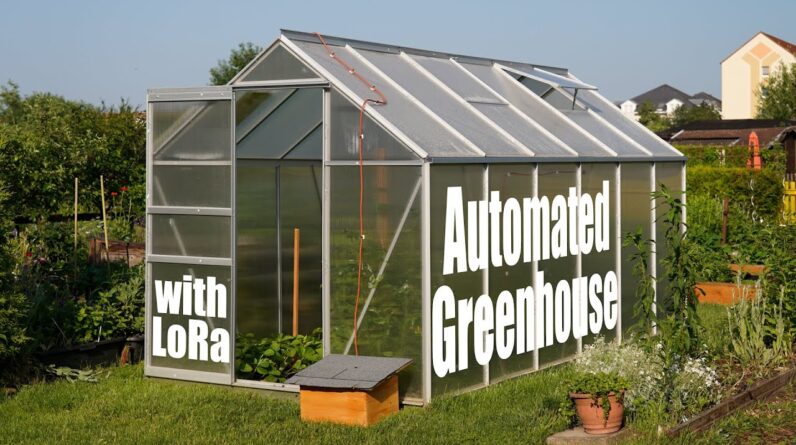
About 4 months ago I built this greenhouse
in my garden which as you can see now houses well growing plants. I got cucumbers, strawberries, sugar melon,
watermelon, tomatoes and bell peppers of which surprisingly not one died yet. But that does not mean that everything goes
perfectly which you can easily figure out if we look at certain leaves or this stem. The problem is a fungus which was caused by
high humidity and could have been avoided if I opened the window more often. But on the positive side, this problem planted
the idea of an automated greenhouse inside my head. This system should measure the temperature,
humidity and soil moisture inside the greenhouse; send this data through a LoRa wireless connection
to a gateway in my apartment 300m away which then uploads it to the Internet of Things
website where I can check on it everywhere in the world.
And as a bonus the system should also be able
to use motors in order to not only open the window to control the temperature and humidity
but also to water the plants if the soil moisture is too low. And of course this automated greenhouse should
get powered through the sun and thus also requires a solar power system. And in this first part of this two part video
series I will show you how I built the green house, how I wired up the power and sensor
system and what kind of programming is necessary in order to get all the required sensor data
into the internet.
This video is sponsored by JLCPCB, where you
can now buy 5 pieces of 4 layer PCBs for a price of only 5$. So why not upload your Gerber files today
in order to experience their 24h fast production time, super quick delivery and excellent quality
PCBs. To start off this project I searched for a
big yet affordable greenhouse on the internet and I found this one with measurements of
190 by 380cm. As soon as I received it, I opened up the
package which contained the metal foundation and laid it onto my lawn to determine a suitable
spot. Then I cut the grass, marked the greenhouse
square with a spade and started breaking up the grass and afterwards removed most of it.
While doing so I also had the unique experience
of removing a dead tree stump which I will hopefully never have to do again in my life. But anyway as soon as that was done I distributed
the soil in my square a bit more evenly and continued by screwing together the metal foundation
which I then moved into position. After I was certain that the foundation was
level by obviously utilizing a spirit level, I opened up the remaining packages which contained
the main parts for the greenhouse. And according to the given manual we then
connected all aluminum beams with one another through the help of the included connector
pieces and screws. Now this part sounds like it was simple to
do but in reality it took quite a while to find the correct aluminum parts and connectors
since the manual was not always that easy to follow.
But nevertheless after a few hours we completed
the metal construction on the lawn before we moved it all over to the foundation to
which we then secured it with more connectors and screws. At this point all that was left to do was
to add the plastic windows which had to get secured in place with dozens of clips. And just like that the greenhouse itself was
successfully built. Now at this point I do not want to bore you
with plant growing tutorials, so let’s just say that suddenly lots of plants appeared
in my greenhouse and let’s instead continue with the electronics. There we can distinguish between the power
electronics and the automation electronics. For the power electronics we need a 12V lead
acid battery, a solar panel and a solar charge controller and luckily for me I had those
three components laying around from previous projects. To be specific I got this 12V 44Ah car battery
which is a bit of an overkill considering that the sensor system will ultimately only
draw around 24mA; but the big capacity will come in handy when later trying to power motors.
Then I got this 10W 12V solar panel which
in combination with this generic solar charge controller will charge up the battery with
a current of up to 0.56A. To test this I wired up the power electronics
system in my garden according to this wiring diagram. Sadly though the sun didn’t feel like working
with me that day but trust me when I say that later when the sun was shining, the battery
was charging without any problems. So next I ordered myself this wooden chest
from the internet into which all the electronics will fit later on. Before putting them in there though I added
a layer of wood glaze to the chest in order to protect it better from the elements.
Next I also created two small wood blocks
and one big square of plywood with the help of my jigsaw. I added the two wood blocks on top of the
chest lid with screws and then mounted the big plywood square on top of it all at an
angle. And as you would have guessed at this point,
this is the roof of my electronics housing which means I also had to add a bit of roofing
paper. So with the housing being completed, I got
myself lots of this silicone wire with 2, 3 and 5 conductors inside which is even suited
to be mounted inside a sauna. What I did next was adding the solar panel
to the roof with Velcro tape to which I then also secured one silicone wire through the
help of wire pedestals and zip ties. I then soldered this wire directly to the
solar panel before I positioned the chest enclosure in front of the greenhouse. There I then drilled 4 more additional holes
into the chest of which I immediately used one in order to guide the solar panel wire
through.

Inside the chest I wired up the solar charge
controller to the battery and solar panel like I described it before and just like that
the power electronics parts was done and it was time to move on to the automation part
starting with this PCB I ordered from the internet. As you can see it features an Arduino microcontroller
as well as an RFM95 LoRa Transceiver. Besides this board we will also need capacitive
soil moisture sensors of which I will be using two, one on each side of the greenhouse, as
well as such a BME280 temperature and humidity sensor and also a LoRa Gateway like this LG02
one about which you can also learn more in my LoRa video.
The general working principle pretty much
stays the same like I described it in the beginning but let me add that the Arduino
will send out the data every 60s and we will be using LoRaWAN
So what I did first was hooking up all of the sensors to the LoRa board for a first
test run according to this schematic which will pretty much not change later on. You might also have noticed that I added an
additional 5V regulator on the power input which was definitely mandatory to add because
the board apparently cannot handle 12V.
But anyway the soil moisture sensor outputs
an analog voltage from 0 to 3V depending on how moist the earth around it is. And the BME280 sensor uses an I2C interface
to send over its temperature and humidity data which means we could use its datasheet
to write proper I2C code but then again there also exists a simpler to use Arduino library
for it. With those information in mind I firstly created
a simple example code that outputs all of the sensor data through the serial monitor
and after using an FTDI breakout board hooked up to the serial interface of the LoRa board
and uploading the code, it seems like everything works just fine. That was the easy part though because now
it was time to establish the LoRaWAN connection for which I not only had to sign up on the
Things Network site and edit the settings of the LoRa Gateway but I also had to use
some rather complicated code.
However this process was surprisingly simple
to do because the Gateway manual describes in detail how to set everything up. Before uploading though I had to connect two
of the RFM95 board pins to two pins of the Arduino because the utilized LoRaWAN library
requires them. And after uploading the final code to the
Arduino LoRa board, we can see on the Things Network site that the data gets uploaded successfully
in HEX which converted into ASCII turns out to be our measured temperature, humidity and
analog values for the soil moisture sensor, awesome. That means it was time for me to design a
small housing for the BME280 sensor and 3D print it before I once again headed into my
garden.
There I soldered the wires to the two soil
moisture sensors as well as the BME280 sensor and then waterproofed the soil sensors with
a layer of nail polish. Afterwards I secured the BME280 sensor with
its wire inside the greenhouse to the wall with wire pedestals and zip ties and pushed
the soil sensors into well the earth. Last but not least I drilled three holes into
the foundation of the greenhouse through which I then guided all the wires which ultimately
got soldered to the LoRa board inside the chest. And as soon as the power wiring was also done,
the first part of this project was basically complete and if we once again check the Things
Network site you can see that everything still works fine. I hope you enjoyed this video, if so don’t
forget to like, share, subscribe and hit the notification bell.
Stay creative and I will see you next time..
As an Amazon Associate I earn from qualifying purchases.