
As an Amazon Associate I earn from qualifying purchases.

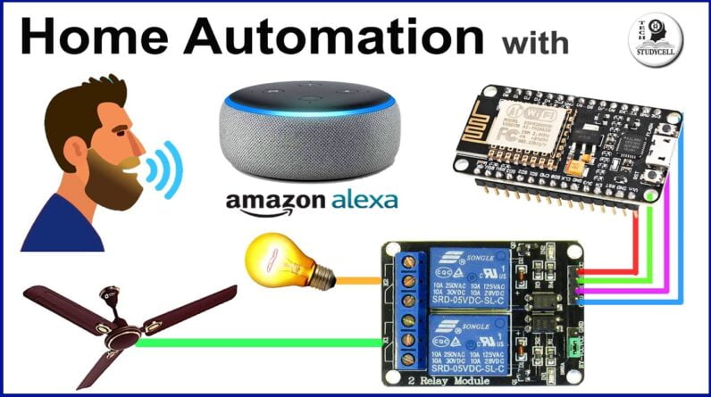
Hello Friends!! Welcome to Tech StudyCell. Today we will make a simple home automation
project using Alexa. For this project, we don't need any custom
design PCBs or any third party IoT platforms. We just need a relay module, NodeMCU or ESP32
board, and the Alexa smart speaker. So let me show you, how it works? "Alexa, TURN ON ALL LIGHTS". "Alexa, TURN OFF ALL LIGHTS". "Alexa, TURN ON RED BULB". "Alexa, TURN ON CFL". OK. "Alexa TURN ON YELLOW BULB". OK. And during the video, I will
share the complete circuit diagram, and also explain the code for this project. So that you can easily make this home automation
project for your home. So let get started. [music] For this project, you just need a relay
module and a NodeMC board. But instead of NodeMCU, you can also use the
ESP32 board. In this project, I will use the NodeMCU board. You can refer this circuit diagram to connect
the Nodemcu with the Relay module.
But to make the circuit compact and give the
project a professional look, I have designed a PCB for this project and order it from JLCPCB. But as I said, you can also make this project
without using any custom design PCB. But still, if you want to order any custom
design PCB from JLCPCB, you have to follow 3 simple steps. first, upload the Gerber file, then select
the masking color and the quantity, and place the order. If you select the faster delivery service,
then you will get the PCB within a week. And as you can see, you can easily get the
good quality PCBs at affordable prices from JLCPCB.
Now I will quickly solder all the components
on the PCB, I have also shared the component list for the PCB in the description. Now, I will connect the NodeMCU on the PCB. After that, we will go to the codding part
of this project. This is the code I have used for this project,
you can download the code from the description. Before uploading the code, first, you have
to copy these two URLs and goto File –> Preferences and paste it here. After that, you have to download the ESP8266
or ESP32 board. For that I will go to Tools –> Board –> Boards
Manager and then here you have to type ESP8266. Now you have to install this board. But here I have installed the old version,
which is 2.5.1. I have faced some issues with the latest version. So if you face any issues with the latest
version then you have to download and install the old version, which is 2.5.1 version of
this ESP8266 board. And if you use ESP32 for this project, then
you have to download and install this board.
After that, I will install the ESPAlexa library. You can refer this link or you can goto Sketch
–> include Library –> Manage Libraries. And here you have to type ESPAlexa. I have already installed it. I have modified one of the basic example sketches
of the ESPAlexa library for this project. As you can see, for the ESP32 board it will
include this library, else it will include this library. Now you have to do two more changes before
uploading the code. Here, you have to enter the WiFi name and
here you have to enter the wifi password. After that, you have to set the device name. As I am using 5 devices, so have given the
individual names for each device. You can give any names to identify that particular
device. If you refer the same circuit, then after
doing these changes you can go to Tools. Select the NodeMCU board or if you are using
ESP32 then select the ESP32 board.
Select the proper PORT, then click on the
upload button. Now, let me quickly explain how the code works. First, I have defined all the GPIO pins which
I have used to control the relay module. And these are the callback functions to control
the individual relays. And if we go to the void setup(), then first,
we have defined all the relay pins, then we are calling the connectWifi() function to
check if the wifi is connected or not.

So if we go to the function, it will return
a boolean value. So if the WiFI is connected, then we are adding
all the devices with this function, else we will print this error message in the serial
monitor. Then in the void loop(), we are calling this
"espalexa.loop()" function to control individual relay from Alexa. And here this callback function I will use
to control the relay 1. Here you can see, if the brightness is 255,
then we are turning on the relay, else we will turn off the relay. Now if you are using an active LOW relay module,
then you have to change it to LOW, and here you have to change it to HIGH. Each relay has it's own callback function
to control the relay module from Alexa. If you go through the code, you can easily
understand how the code works. But still, you face any problem, let me know
in the comment section. Now, I will connect all the home appliances
with the relay module as per this circuit diagram. As you can see, I have connected all these
five lamps with the relay module, and I have given 5 volt supply to the NodeMCU from the
mobile charger.
Now, I will configure the Alexa App to control
these five lamps. So let me open the Amazon Alexa App. Tap on Devices, then I will tap on this "+"
button to add the devices and tap on the "Add Devices". Here I will select "Light" and here I will
select the "Other". Now I will tap on the "Discover Devices",
it will take some time and during this time the Alexa smart speaker and the NodeMCU should
be connected with the same wifi. Here you can see, it found five devices.
I will select the "Choose Device" and here
you can see, these are the device names which we have given in the code. I will add all the devices one by one. I have added all the devices with the Alexa
App. Now I will tap on "Done". Now, in the lights you can see, these are
the devices that we have connected. Now, we can easily control these five lamps
with Alexa. "Alexa, Turn on all lamps". OK. "Alexa, Turn off blue lamp" OK. "Alexa, Turn off RED lamp" OK. But there is one limitation, the Alexa speaker
and the NodeMCU should be connected with the same WiFi. If you liked this project, please give a Thums
Up, and share it with your friends, don't forget to SUBSCRIBE for more such home automation
project.
Thank you for watching have a great day..
As an Amazon Associate I earn from qualifying purchases.