

As an Amazon Associate I earn from qualifying purchases.

In a previous project video of mine I showed you how I created a photovoltaic off-grid system which to this date works without any problems but what I noticed in the comment section back then was that many of you are stated that a flat mounting on the roof is not ideal Which I do agree with Not only does the panel gets out more easily but this mounting also decreases the air flow another panel and thus the cooling and Also the power outputs since the Sun is hitting the panel more often at a sharp angle So why did I mounted it this way then and not at an angle? Well, the reason is that it is not easy to spot that way and thus will most likely not get stolen But anyway, since I recently got interested in how much energy I'm actually losing due to the position of my panel I will conduct a small solar tracking experiment in this video Which will hopefully turn out in my favor and thus let me sleep at peace once again Let's get started [music] This video is sponsored by JLCPCB one fact about them.
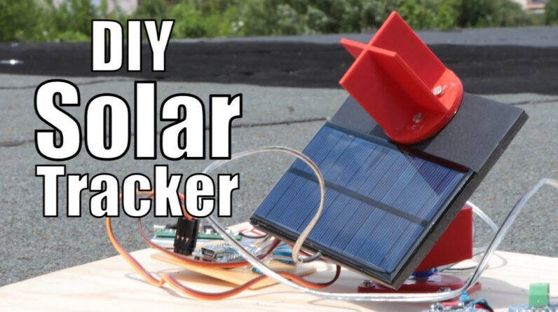
You can easily find the tracking number invoice and production process of your PCBs in your account and Easily order more PCBs of your old design through the reorder button without having to upload your Gerber files once again For this experiments I will be using two Hopefully identical solar panels with an open circuit voltage of 6 volts and a maximum output power of 1 Watts 1 will be placed on a flat surface while the other one will be mounted to a solar tracker which like the name implies Follows the position of the Sun in order to maximize the power outputs of the solar panel Both panels will be connected to power logger and loads which will later reveal how much more energy the solar tracker system harvested and With the execution of this experiment explains.
Let's get started by building the solar tracker To move the panel in a circular manner and also in an uptown movements I went with this mini pencils mechanical system Designed by fbuenonet Printed the three-year required parts with my 3d printer which took around 4 hours Afterwards, I mounted the base plates to a piece of woods with some leftover screws and Got myself to SG90 servos which will be used to move the whole system. I Positioned the fitting accessory of bits in the base plates and added the motor to it Which by then covered with the second 3d printed parts To its I also added an accessory part of the servo Mounted the second servo to the third and last 3d printed parts with screws and then finally completed the mechanical system by combining the two pieces with an additional screw and As you can see the movement of the solar tracker was possible But of course for the servos, we need an electrical signal to move them accordingly for that I created this small schematic whose components I connected to one another on a piece of perfboard and Once I was getting close to finishing the circuits I noticed that the most important components the photo resistors were not properly utilized yet In case you're wondering photo resistors are like the name implies resistors Would change to the resistance according to how much light hits them With lots of lights.
We got a small resistance and in darkness, we got a high resistance. I wanted to mount four of them on a circle roof wall divided segments so that for example when the left side is dark the motors rotate the system clockwise and If the lower side stock the motors move the solar panel upwards This way the system will always follow the brightest light source so I constructed d described circular object in 1 2 3 D design and Once again used my 3d printer to create it Afterwards, I enlarge the holes for the photoresistor leads push them in place and secure them all with a bit of hot glue Now to mount the solar panel and the photoresistor setup to the mechanical system I created an eleven by nine point five centimeter piece of foam plastic To which I firstly secured the solar panel with hot glue After I sold our two wires to its terminals then I created a 24 centimeter hole in the top section of the foam plastic and Secured the photoresistor set up there with hot glue as well to complete the solar tracker I added wires to the photo resistors Which I then connected to the perfboard circuits and secured the fantastic to the mechanical system with hot glue Along with the 1 kilo Ohm resistors, the photo resistors build up a voltage divider Which creates a high voltage when the photo resistor stark and a low voltage when it is illuminated So after connecting these servos to the circuits and powering it with a 5v power source.

It was time for programming in a nutshell, I utilized the timer one of the arduino atmega328p microcontroller in order to generate servo compatible pwm signals which are constantly alter depending on whether the lower upper left or right side of the photo resistor setup is illuminated and After uploading the codes I tested the setup of a flashlight Which seems to work without any problems, which means it was time to complete the experimental setup with my power logger.
I built this one in a previous project video So feel free to watch it if you want to understand how it works or if you want to create one for yourself anyway, after connecting the logger to the remaining unmounted solar panel, I Connected a potentiometer loads in order to determine the maximum power point of the system Which according to my calculations should be reached with a resistance of around 3150 ohms But since we would never reach the maximum power at a higher brightness level with this resistor I rather replaced it with 4 , 200 Ohm resistors in parallel Which should be able to get us close to 1 watts That means the flat solar panel setup was complete but sadly in order to conduct both measurements at the same time I had to create a second power logger for the solar tracker which took quite a bit of time But once that was done, I hocked the solar tracking solar panel up to the power logger along with the 50 Ohm loads and started the outdoor experiments Now I let the two systems create electrical energy from solar energy for around 2.5 hours while making sure that the systems locked all the data onto the SD card and the solar tracker are truly followed the sun's movements and After waiting for that long, the flat solar panel delivered a total energy of 10,345 milliwatt hours while the solar tracking solar panel delivered about 11891 milli watt hours That is a difference of 15% more energy, which is not that bad of Course we have to keep in mind that this experiment was rather short was executed around noon Did not utilized an MPPT methods and the solar tracker was limited in its movements But since we know that the Sun angle of only 45 degrees can decrease the power output by 30% We can assume that through the day especially during the morning and evening time My solar panel might be missing out on around 20 to 30% of the possible solar energy Which is affect that from now on I have to live with Nevertheless.
I hope you learned a little bit about photovoltaic systems through this video If so, don't forget to Like share and subscribe Stay creative, and I will see you next time!.
As an Amazon Associate I earn from qualifying purchases.