Today we gonna build what in the past was
considered a pretty futuristic technology. It’s a clap switch, so basically you just
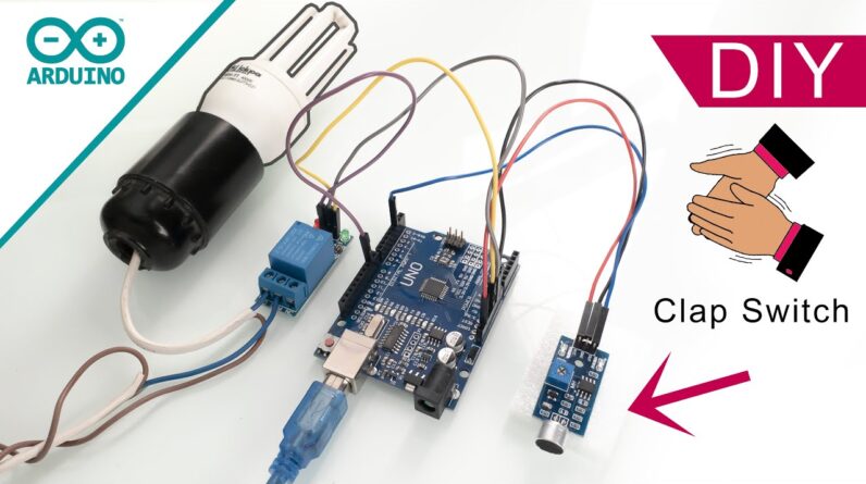
clap to control your lights, all you need to do is just clap two times. And building such device nowadays is pretty easy, so stay tuned, and let’s get started. Hi Humans welcome to Electrical Projects channel. To make this device work we don’t even need to solder anything… but we need some components. The most important is an Arduino. Well, Arduino is the brain of the whole project. Arduino’s job here is to recognizing the correct clap pattern, two claps in our case. If it’s just one clap it’s not gonna do anything. And the first what we have to do is to flash the Arduino. The Link to the code you will find in the description. This is pretty simple. Let's connect it to a computer, and flash it. After it’s done, next what we have to do is to connect everything. Let’s start with the microphone.
So let’s connect ground and 5 volts. The output of the microphone lets connect to PIN number 2. Now, let’s connect power to the relay. Let’s connect ground first. And now let’s connect 5 volts… but oh no, we have a problem… there are no more 5V pins here, and I need 5V. What should I do? Use a breadboard? Wrong! On Arduino Uno IOREF pin is the same as 5V pin, so let’s just connect it here and keep this project simple.
And now let's connect the input pin of the relay to Arduino pin number 9. Now let’s power up everything. Now we have to adjust the sensitivity of the microphone. If everything works properly after one clap Arduino should light up build in LED for a short period of time. If you clap two times in a sequence the relay should switch. If it works, it mans you can control any device. A light bulb for example… let’s connect it. And be careful with the mains electricity… they say it can kill! and I think it’s a bad idea to test that assumption… So let’s just be safe. Now let’s see how it works, and test the device. As you can see it recognizes the claps very well. But we still have a problem;
The problem is that the microphone is sensitive to a wide range of sounds, including voice, which leads to false light switching. You can obviously decrease the sensitivity of the microphone in order to fix the problem, but then you will have to clap very loud and you have to do this very close to the microphone, which is not very convenient.
Hmmm, if only there was a way to fix that… and actually there is, but it’s a bit advanced. In order to fix the problem, we need to understand the difference between clapping and voice sounds in terms of frequencies. The clapping sounds have high frequency components, so in order to fix the problem we need to make this microphone module more sensitive to high frequencies and less sensitive to low frequencies, and that is what I am going to do. The 100nF capacitor that is connected in parallel with the microphone we gonna remove permanently, another 100nF capacitor I am going to replace with 1nF capacitor which gonna make this module less sensitive to low frequencies. So let’s solder 1nF capacitor. If you don’t have an SMD capacitor you can use a regular one. After cleaning it looks perfect, so let’s connect it back and test it.
Let’s adjust the sensitivity. It works much better now and it doesn’t react to my voice. My assumption about frequency differences is correct. But there is still one more capacitor that can be removed to increase response to higher frequencies, so let’s remove it. Now let's test it! Now, it’s perfect. It’s not sensitive even to a loud voice, but sensitive to clapping. I am very satisfied with the results. As always the code can be improved, but it’s already good, it has some false triggering prevention. Let me demonstrate. And that’s it, links to all of the components for this project you can find in the description to this video. Thank you very much for watching! And see you in the next one..
As an Amazon Associate I earn from qualifying purchases.


