
As an Amazon Associate I earn from qualifying purchases.

Hello friends, welcome to Tech StudyCell. In this
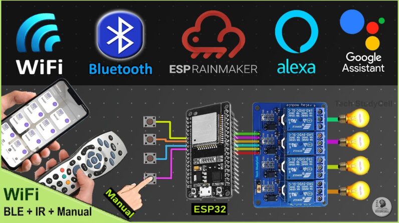
video, we will make another home automation system to control the appliances with Google Assistant,
Alexa, Bluetooth, IR remote and Manual switches. if the ESP32 is not connected with WiFi, still
you can control all the appliances from your smartphone through Bluetooth. and you can
also use IR remote and manual switches. for this project I have used all the free
tools. so everything is free. and you can make the circuit without using any PCB. and during
the video, I have shared the complete circuit, source codes.
So after watching the complete
video, you can easily make this project. now before going to the details, let
me show you how this project works. here you can see, the blue LED is glowing, which
indicates now ESP32 is connected with the Wi-Fi. first, let me control the third lamp with Google
Assistant. "Hey Google, turn on switch 3". you can you see the lamp turn on. now let me use
Alexa to turn it off "Alexa, turn off switch 3". the lamp turns off. now let me turn off the
Wi-Fi to show you how it works without internet. after turning off the Wi-Fi, you can see
the blue LED is not glowing, so it is not connected with Wi-Fi.
And here it is showing no
internet connection in Amazon Alexa app. first, let me control appliances with Bluetooth. you can
use any Bluetooth module, I've already made an App in MIT app inventor to control the appliances. you
can download it from the video description. first, let me connect BLE module, I will just connect the
module and here it is showing connected. now I can easily control the lamps with this Bluetooth app,
as you can see. and I can use this button to turn off all the lamps together. and I can also use
the IR remote to control appliances. and I can again use this button to turn off all the lamps
together. now let me use the manual switches. As I said, you can use any Bluetooth or BLE module
for this project. but if you use this BLE module then you can cover more distance, so you can
control appliances from other rooms. now let me turn on the Wi-Fi again. after turning on the
Wi-Fi the ESP32 will automatically connect with Wi-Fi and this blue LED will turn on. now again
I can control it with the Amazon and Google. So this is a very useful IoT project, you can
easily make for your home.
Now without any further delay let get started… These are the required
components for this project. for the Bluetooth control, you can either use HC-05 Bluetooth module
or any BLE modules. in this project, I am going to use this RYBG211 BLE module from Reyax. as this
is a BLE module so it consumes very low energy and apart from that, you can connect it with 8
client host at the same time. with this module you can also cover more distance than other
Bluetooth module. so if you want to use this BLE module you can find a purchase link in the
video description. now We have to connect all these components as per this circuit diagram.
if you want to use HC-05 Bluetooth module, then you can refer to this circuit.
I have given
the 5 volt supply to the Bluetooth module, ESP32, relay module and IR receiver. you should use
a IR receiver with a metallic case. now if you want to use latched switches, then you can refer
to this circuit. you just have to connect switches across the GPIO pins and ground pin. now if
you want to use BLE module for this project, the you can refer to this circuit. here I have
used Reyax RYBG211 BLE module. for this module, I have given the 3.3 volt supply from the ESP32. and
here I have just use the TX pin of this module, and for the serial communication I have used the
RX2 pin of the ESP32.
And again if you want to use pushbuttons, then you just have to connect the
pushbuttons across the GPIO pin and ground pin. as you can see the circuits are very simple
you can easily make it without using any PCB. but just to make the circuit compact and to avoid
any loose connections, you can use these PCBs for this project. for this PCB I have used the SMT
service of the Jlcpcb. you can download the Gerber files for both the PCB from video description, and
order it from the jlcpcb. in jlcpcb, you can also use their PCB assembly service absolutely free.
you just have to pay for the components. to use their PCB assembly service you have to generate
3 files. you have to generate the PCB Gerber File then BOM file and peak and place file. then
visit the jlcpcb, you can find the link in the description. then you have to upload the
Gerber file. after that if I will scroll down, now I want all the components should be soldered
on the top side of the PCB.
Now I have to upload the BOM file and pick and place file. here
you have to confirm all the components, that you want to use for the Assembly service. you
can see it is showing approx footprint. and you will get all the details here. after checking all
these, click on save to cart, and place the order. in my case I have received is PCB from jlcpcb
within a week. and as you can see the packing is really good and also the quality is very premium
in the this affordable price.
These are the source codes for this project. you can download all these
codes from our website or iotcircuithub.com. just visit the article, link given in the description.
Then you can download all the codes from these buttons. after downloading, first, you have to
get the HEX codes of the IR remote buttons. for that you can use this code. In this code, you
can see you have to install IRRemotelibrary 3.6.1 version. after that, upload this code to
ESP32. Then connect the ESP32 with the IR receiver as per this circuit. then open the serial monitor.
now press the IR remote buttons, you will find the related HEX codes will populate in the serial
monitor. now save all these HEX codes. These are the main sketches for this project. if you want
to use latched switch, then you can refer to this code. and for the pushbutton you have to upload
this code. let me open the code for the button. to program the ESP32 for RainMaker, you need to
install the 2.0.3 version of the ESP32 board. for that, first, you have to update the preference
url.
You can copy these 2 URLs,then go to File, Preference and here you have to update these two
URLs. after that you have to go to tools, Board, then go to Boards manager, and from here you can
update the ESP32 board to the 2.0.3 version. after that, you need to install these libraries. I
have also mentioned the version required for this project. for your to install this version
for these libraries. here you can see this is the Node name. you can change this node name.
under this Node, you will get these devices and you can also change the device names. Alexa
or Google will identify the devices with these names. I have given the name Switch1 Switch2….
like that. you can give any other names like room light study lamp as per your requirement.
after that, you have to update the HEX codes of the IR remote buttons.

These are the hex
code for the IR remote buttons. In my case, I have used the button "1" to control the relay-1.
so I will just copy the HEX codes of the button-1 and here I will paste it. in this way, you
have to update the HEX codes of all the IR remote buttons. after that, these are the GPIO
pins, I have used for this project. and for the serial communication with the Bluetooth module,
I have used these two pins.
Now let me go to void setup(). here you can see, that I have used
these two pins for the serial communication with the Bluetooth module. now let me go to
the void loop. in the void loop, I am calling these two functions ir_remote() is for IR remote
control and with this Bluetooth_control function, I will control the appliance with Bluetooth.
let me go to the Bluetooth_control function. Here you can see, first, we are checking if there
is any data available in the serial terminal, which have defined to communicate with Bluetooth.
then we are comparing the data with the predefined values. If the data is "A1" then we will turn on
the relay-1. and if the data is "A0", then will turn off the relay-1. here I am using the active
low relay module.
So if it receives a low signal the relay will turn on and if it receives a HIGH
signal, the relay will turn off. if you go through the code, you can easily understand it. and if you
refer to the same circuit, you just need to change the HEX codes of the IR remote buttons. and if you
want, you can change the device names. after that, go to tools, select the board as ESP32 Dev module,
and the partition scheme will be RainMaker. then select the proper port. now hit the upload
button. after programming the ESP32 now I will add the devices to RainMaker. for that, I will
press and hold the boot button for four seconds. then I will release it. now you can use
this QR code to add the devices. for that open the "ESP RainMaker" app. and here first
I have to turn on the Bluetooth and location. now tap on "Add devices", and scan the QR code.
you can use the same QR code. I will share this QR code in the video description.
Now I have to pair
it. Then enter the Wi-Fi credential. now, this may take some time. now will tap on done. you can see,
all the devices added. Now I will quickly link the Amazon Alexa and Google Assistant with the ESP
RainMaker. so I will go to settings, select the voice service, then select Amazon Alexa. then
I'll tap on "Link with Amazon Alexa". Here I will tap on LINK. Now I will tap on Continue with
Google and select the Email ID. We have connected devices with Alexa. now let you quickly open
the Google home app. I have already created the home. Now go to setting, tap on "works with
Google". here search for ESP RainMaker, then tap on "Continue". after that, I will go to Dashboard
of the Google Home.
In the dashboard, you can see all the devices added. Here you can see, that
I have connected the BLE module with ESP32. As I said, you can also use the HC-05 Bluetooth
module. now to control the relays with Bluetooth, I have made an app in MIT app inventor. you can
download this app from the video description. let me install this app. I have not yet submitted this
app to the Google play store, so you may get some warning while installing it. let me open the app.
Now if you use HC-05, then you can control relays with the Bluetooth Switch window. but there I have
connected a BLE module, so I will go to be BLE. I will just tap on BLE for that. now I have to turn
on the Bluetooth. let me give the permission. first, I have to pair this BLE module. so I will
go to the mobile Bluetooth, then I'll tap on the BLE name and tap on "Pair" to pair the BLE
module.
Then I will go to the Bluetooth app. now I will connect the module with the app. so I
will tap on "connect" and select the module name. now here it is showing connected. so I can control
the relays with this app. and I can use this button to turn on all the relays and this button
to turn off all the relays. you can use any other BLE module, for that you have to enter the service
ID and the characteristics ID and tap on submit, then you can able to control the relays. for
the Reyax, I have already made it default, so you don't have to enter any details for this
BLE module. now if I go to App details, here you can see to turn on the switch-1, I am sending
"A1" to the Bluetooth module, and to turn it off, I am sending "A0".
With these details, you can
use this app for any Bluetooth projects. I have not yet found such an app to control the relays
with the BLE module. and as I said, if you want to use the HC-05 Bluetooth module, you have to use
this window Bluetooth Switch. and again you have to pair the module first, then you have to connect
it and control the relays with these buttons. and here you can see, I have also connected the IR
receiver. so I can also control relays with the IR remote. let me turn on some relays, and I can use
this button to turn off all the relays.
so this is a very useful IoT project, as you can control
relays with Bluetooth, IR remote, and manual buttons and apart from that you can control the
relays with the ESP RainMaker, Amazon Alexa, Google Home, Google Assistant. and you can make
this complete project using the free IoT tools. If you find this project helpful then please give
a thumbs up and share it with your friends. I will really appreciate it if you support or work on
Patreon, you can find the link in the description. and don't forget to subscribe for more such
projects. thank you for watching have a great day..
As an Amazon Associate I earn from qualifying purchases.