
As an Amazon Associate I earn from qualifying purchases.

If you watched my video about essential tools
that you will need for creating electronics projects then you know that the lab in my
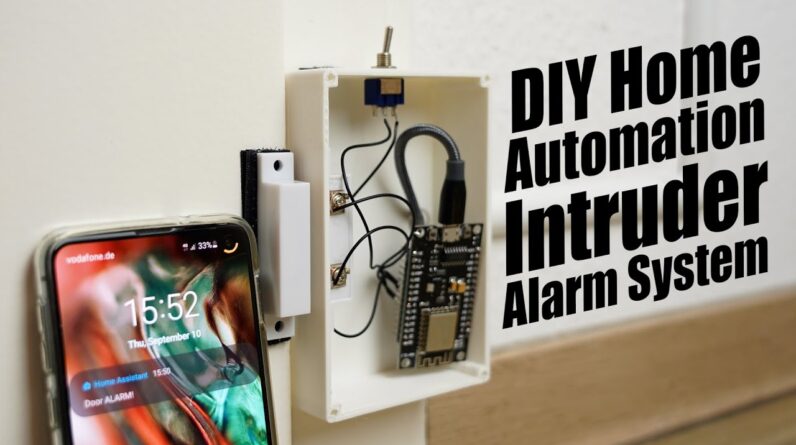
apartment houses some rather expensive equipment which I don’t want to get stolen. So I was thinking about creating an intruder
alarm system which basically sends me an alarm notification to my smartphone whenever my
apartment door gets opened while I am not home. Now the hardware site of things is pretty
straightforward by using an ESP8266 microcontroller that comes with Wi-Fi in order to send over
the status of a magnetic reed switch positioned on the frame of the door while a magnet gets
secured to the moving part of the door.
The reed switch basically closes its contact
when the magnet gets too close and thus we got two defined statuses that either indicate
whether the door is open or closed. The only question left to answer was how to
do the software and I was actually thinking about integrating this small project into
my previously introduced home automation system with Sinric. But then one of my Patreon supporters suggested
that I should check out the esphome project which I promptly did and let me tell you after
having a closer look at it as well as the home assistant software for which it is actually
just an add on, I was convinced that I need this in my home. And in this video I will not only show you
how to create this intruder alarm system through the help of a Raspberry Pi, an ESP8266 and
some additional components but I will also show you how to use the home assistant software
to for example turn on your lights, gather sensor data or automate a couple of things.
Let’s get started This video is sponsored by JLCPCB! Feel free to visit their website JLCPCB.com
to not only find out what awesome PCB and Assembly services they offer but also to easily
upload your Gerber files and thus order affordable and high quality PCBs quickly. First off we need a Raspberry Pi and luckily
for me I got this old Raspberry Pi 3 lying around. The reason why we need such a Single Board
Computer is that we need some kind of server for the home assistant software which the
Pi will be. That means it will connect to our router and
thus network and act as a bridge between all the ESP devices and our interaction devices
like a PC or smartphone. This way we can not only program the ESP boards
through a web user interface that the home assistant software comes with, but we can
also for example directly turn on lights with it or it can visually represent gathered temperature
data or the status of my door sensor.
So let’s get started by grabbing a suitable
micro SD Card, inserting it into a computer and downloading the fitting image file for
your raspberry pi. After extracting it, we can use the balenaEtcher
software to write the image to the SD card. After that was done, I created two new folders
on the card called config and network into which I created a new file where I entered
the information of my home network. You can of course find more information about
this process on the home automation site for which and many more useful sites you can find
the links in the video description. But anyway as soon as that was done, I inserted
the SD Card into the Pi and supplied 5V power to it.
At this point we basically have to wait for
a bit and after a couple of minutes you can check your router to find the IP address of
your Raspberry Pi which should now be called home assistant. After then opening this address through the
Port 8123, we can see that the home assistant was still getting installed. But after around 15 minutes of waiting, I
was able to set a username and password and thus was able to finally have a look at the
user interface.
So let’s continue by navigating to supervisor
and add on store where we have to search for and install ESPHome. As soon as that was done we can basically
start the add on and open it and to not surprise we do not have an ESP node yet. To change that we click on plus. There I named my first node lights, the device
type is a NodeMCU which is the style of EPS8266 I will be using and finally I entered my Wi-Fi
information and thus we are basically done. Now in theory we could hook up the ESP board
to the computer and see the serial port in the software but for me this never worked
out. So I had to compile the firmware, download
it and then I had to us the provided ESP Home Flasher which always worked like a treat. And after once again powering the ESP board,
we can see in esphome that it is now online and that is the point where we can edit its
code.

What I added was a simple switch setup on
the Pin D5 which I will call lights. And after clicking upload, the code complies
and automatically sends it over to the ESP through Wi-Fi. And if we now switch over to configuration
and integration, we can see that the software discovered an esphome device which we can
add to the dashboard. Here we can easily turn the switch on and
off which as you would expect pulls the D5 pin of the ESP board to the supply voltage
or GND. In my case I am using an LED as my light example,
but if you get yourself an ESP board with relay then you can also easily switch light
bulbs on and off.
Of course you cannot only turn on the lights
manually, but also through automations which you can find under configuration. There we can set a trigger like for example
the sunset at which point an action should be performed which is in our case turning
on our lights. This way you can easily automate your entire
home to your likings which is pretty awesome and easy to do. Moving on though, to control this system through
a smartphone we firstly need to download the home assistant app. There we now need to add a URL for our home
assistant server which is necessary to access our home assistant through cellular data and
not only when we are connected to the home network. For that there exists a free method with the
help of DuckDNS for which you can find videos on YouTube but I prefer the home assistant
cloud method which may cost a monthly fee after a trial period but on the other hand
it is super reliable and also offers Alexa and google assistant integration.
So after creating an account you basically
get a remote control URL which you can now enter into your smartphone and thus you are
granted access to your home assistant anywhere in the world to turn on your lights. As a next example I got this BME280 temperature
and humidity sensor that I want to add to this system. Luckily ESPHome supports this sensor along
with tons of other sensors, so I only had to copy some of the example code, upload it,
wire up the sensor, add the entities to the dashboard and customize the dashboard a bit
in order to integrate the sensor, super simple. But now let’s get back to the door sensor
for which I not only connected a reed switch to another ESP board but also a toggle switch
according to this wiring diagram. I will flip the toggle switch when I am out
of the apartment for a longer time because I do not want to receive an alarm every time
I open the door.
So after creating a new node and uploading
the standard firmware, I edited the code of the node to feature two binary inputs, one
is the magnetic reed switch as the door and the other is the toggle switch as my on vacation
input. And after uploading this code and adding the
entities to the dashboard you can see that everything works just fine so I continued
by creating an automation which sends out an alarm message to my smartphone when the
door is being opened and the on vacation switch is activated.
After saving it you can see that as soon as
both of those events occur, I do in fact get a notification, beautiful. So it was time to mount the Raspberry Pi into
its own enclosure which coincidentally can be mounted inside my distribution box into
which I also added a 5V power supply that I quickly wired up in order to power the pi. For the esp system however I 3D printed myself
a nice enclosure which I designed in fusion 360. Then I hot glued the reed switch inside the
enclosure, mounted the toggle switch, wired everything up and secured the enclosure to
the door frame with the help of Velcro tape. I then used the same tape to secure the magnet
next to the enclosure. Then I plugged a 5V power supply into an outlet
above the electronics and secured a cable duct to the wall which will guide the micro
USB cable to the enclosure. And after plugging the micro USB cable into
the ESP and closing everything up, this project was basically complete and as you can see
it works like a charm. I hope you enjoyed this video, if so don’t
forget to like, share, subscribe and hit the notification bell.
Stay creative and I will see you next time!.
As an Amazon Associate I earn from qualifying purchases.