
As an Amazon Associate I earn from qualifying purchases.

Hello, Dejan here from HowToMechatronics.com
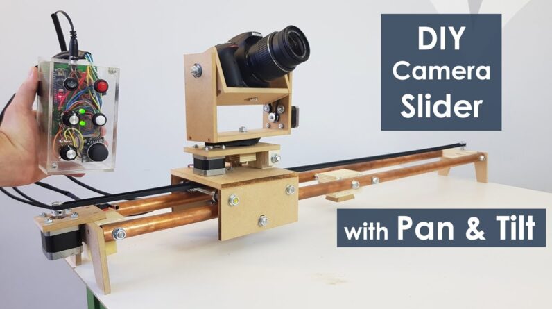
In this video we will learn how to make a motorized camera slider with pan
and tilt head. This project is 100 % DIY, built with cheap materials
like MDF and plywood and controlled using Arduino, three stepper motors, some
buttons and a joystick attached on a custom-designed PCB. Despite this, the end
result is quite impressive with super smooth camera moves enabling us to get
professional-looking cinematic shots. Using the controller we can either
manually move the camera around or we can set start and end points and the
camera will automatically move from one to the other position.
Also using the
supporting arm we can mount the slider even on a smaller tripod, at any angle we
want and still get a stable movements. To begin with, I designed the slider using a
3D modeling software. You can find download and get all dimensions from
this 3D model on the website article, the link is in the description of this video.
So I started with making the slider rails for which I used 22 millimeter
thick copper pipe. I decided to make the slider 1 metre long so I cut two
pieces to 1 meter of length. Copper pipes can easily oxidized so therefore we need
to polish them with a metal polish. In my case, I didn't have one so I used the
toothpaste for that purpose. This wasn't a perfect solution but still I could
notice a difference and got the pipes a bit cleaner. Then I moved on with making
the wooden base on which the two pipes will be attached and also it will serve
for mounting the slider onto a tripod. Using a circular saw I cut two pieces of
21 millimeter thick plywood and glued them together in order to get a single
thicker piece.
Then using a solid wood I made a replica of my tripod mounting
plate and attached it to the plywood piece using a
wood glue and a screw. Now the slider base can be easily mounted on a tripod.
I will mount the slider rails to the base using 8 millimetres threaded rod so I
made two holes in the wooden base and inserted the 138 millimetres long rods
which had previously cut them to size. Next I head to drill 8 millimetres holes
in the pipes which can actually be a little tricky. For that purpose I made a
simple jig where I raised the pencil to a height of 11 millimeters or that's half
of the pipe diameter. Then I secured the pipe on a flat surface and using the jig
mark the pipe from both sides. This enables us to get precisely aligned
holes from both sides. So first I mark the drilling points with a sharp screw
tip and then drill them progressively using 2, 4, 6 and 8 millimetres drill bit.
After that I inserted the rails through the threaded rods and using some washers
and nuts I secure them to the slider base.
In similar way, using a piece of
plywood and a threaded rod I've fixed the ends of the rails.
Next is the a sliding platform. Again I used the circular saw for cutting the 8
millimeter thick MDF boards to size according to the 3d model. I also made
some 8 millimetres holes for the threaded rods on which the bearing are
going to be attached. For assembling the platform I use the wood glue and some
screws. Using a cordless drill first I made pilot holes, then made the
countersinks and screwed the 3 millimeter screws in place. Once the
panels were secured I continued with installing the bearing system. The
bearings that I'm using are 608Z with outer diameter of 22 millimetres. Two
washers in a nut between two bearings make enough distance between them thus
enabling good contact with the 22 millimeter rails.
In order to make the platform more secure when using the slider at an angle,
in similar way, I inserted two more sets of bearings at the bottom side of the
platform. At the end the sliding platform turned out to work perfectly. Here we can
notice that now when moving the platform along the slider on my small, not
heavy-duty tripod, the tripod head cannot hold the weight of the platform so I had
to make a supporting arm in order to stabilize the slider.
So using two pieces
of wood as some nuts and bolts I made a simple clamp which can be fastened to
one of the tripod legs. The clamp has a bolt on which the supporting arm can be
fastened. Next I had to make a slot on the supporting arm in order to be able
to position the slider at a different angle.
I made the slot by simply drilling many six millimeters holes close to each
other and then using a rasp I made fine straight lines. This supporting system
ended up working perfectly. I continued this build with adding legs to
the slider, in case I don't want to use a tripod.
I made them out of 8
millimeter MDF. Using a handsaw and rasp I easily got the desired shape
of the legs. Then using some glue and two nuts I secure them to the ends of the
slider. The next stage is building the Pan and Tilt system which will be attached
on the top of the sliding platform. Using the circular saw I cut all needed pieces
with the measurements taken from the 3D model. I used few pieces of plywood for
making the hinge mechanism of the leveling platform for the camera when
the slider is set at an angle, as well as some MDF boards on which I made
appropriate holes for the motor and the bearings for the pan system. I moved on
with installing the stepper motor and the timing belt for the sliding platform. On
one side of the platform I secured the stepper motor with a piece of MDF board
and some screws and bolts and on the other side of the slider I secured an
idler pulley so now I can install the timing belt.
Using two bolts and zip ties
I easily secure the timing belt to the sliding platform. With this step the
sliding mechanism was completely done. I continued with
making the upper parts of the pan and tilt system. According to the 3D model I made
all appropriate holes for the stepper motor and the bearings and glued and
screwed everything together. A friend of mine 3d printed two 80 tooth pulleys for me. In
this way I got 5 times speed reduction relative to the 16 tooth pulley attached on the
stepper motor. Now I needed to make a closed loop timing belt according to my
setup. So I measured how much length of belt I needed, cut it to size and then
simply glued it with CA glue and added a piece of tape on top of it. The CA glue does a great job with rubber, so the closed loop belt worked without a
problem. Next I started the final assembly of the
pan and tilt system. First I secured the tilt motor using some bolts and then
added the two bearings in place while securing them in the slots with some
epoxy.
Then I secured the tilt platform onto the pan platform using some 8
millimetres bolts and at the same time I attached the 80 tooth pulley to it together
with the timing belt. Here I noticed that the belt was a bit loose but I added a
small bearing in the place where the stepper motor bolt goes to act as a
belt tensioner. This worked out so now the belt had enough tension to work
properly. Next I secured the pan motor and added bearings to the top side of
the leveling platform, as well as on the bottom side. Then I inserted a bolt through them, added a thrust bearing, the 80 tooth pulley and the timing belt and on top of
them I added the previously assembled tilt head. Finally I secured it using a
bolt and that's it with this step the construction of the slider is completed.
OK, so next comes the fun part or installing the electronics components.
Here's the circuit diagram of this DIY camera slider project.
So the three NEMA 17
stepper motors are controlled via the three 4988 stepper drivers. For controlling the
slider movement we use the potentiometer
connected to an analog input of the Arduino and for controlling the pan and
tilt head we use a joystick module which actually consists of two potentiometers,
so it is connected to two analog inputs. There's also another potentiometer used
for setting the speed of the automatic movement from the IN and OUT positions.
These IN and OUT positions are set with the help of a push button. This push
button has a pull-up resistor and it's connected to a digital pin of the
Arduino board.

There's also a reset push button, a power switch and a power
jack, as well as the limit switch for the slider and two LEDs for indicating the
IN and OUT status. For powering this project we can use voltages from 9 to 12V.
Next according to the circuit diagram I designed a custom PCB in order to keep the electronics components organized.
I did that using the EasyEDA free online circuit design software.
The circuit had
quite a few connections so I used both the top and the bottom layer and managed
to get functional and good-looking PCB. Once finished with this step I generated
the Gerber file needed for manufacturing the PCB. Then I ordered the PCB from JLCPCB
which is actually the sponsor of this video. Here we can simply upload the
Gerber file and once uploaded we can again review our PCB in the Gerber
viewer. If everything is alright then we can go
on select the properties that we want for our PCB and then we can order our
PCB at a reasonable price. Note that if it's your first order from
JLCPCB you can get up to 10 PCBs for only $2. Nevertheless, after several days
the PCBs have arrived. The quality of the PCBs is great and I must admit that it's
quite satisfying to have your own PCB design manufactured.
OK, so next I moved
on with assembling the electronics components. I started by soldering pin
headers to the PCB. This enables easier connecting and disconnecting of
components when needed. I actually used pin headers for everything except for
the capacitors and resistors which I soldered directly on the PCB. Therefore I
continued with soldering jumper wires to all electronics components. In this way I
can easily mount the components on the controller case and at the same time
connect them to the PCB. As for the controller case I decided to make it out
of 4 millimeter thick transparent acrylic because I wanted all electronics
components to be visible. Again, I used the circular saw to cut the panels for
the case to size. Then using a drill and Forster bits
I made the openings on the front panel for the buttons, the potentiometer, the
power switch and the joystick. After that using a 5 minute epoxy I assembled the
case and as for the front panel I inserted and glued two bolts through
which the front panel can be inserted and secured using some nuts on top of it.
Finally, I started assembling the electronics by inserting the Arduino
board and the three 4988 stepper drivers onto the PCB.
Then I continued with
inserting and securing the buttons and the other components on the front panel.
Once I had them secured I connected the components to the appropriate pin
headers on the PCB. On the side panel of the case I added the power jack and then
inserted the PCB into the case. On the same side panel there's also a hole
through which put jumper wires for connecting the
drivers to the stepper motors, as well as for connecting the limit switch which I
placed it at the end of the slider.
Using some heat shrink tubing I organized the
jumper wires coming out of the controller case and finally what was
left to do is to connect the controller to the three stepper motors and the
limit switch. As for powering the slider I used three 3.7 Li-ion batteries connected in series producing around 11 volts. And that's it, the slider
is done and it works perfectly. Now what's left in this video is to take a
look at the Arduino code and explain how the program works. The program is based
on the AccelStepper library by Mike McCauley. This is an incredible library
which enables easy control of multiple stepper motors at the same time. So once
we include this library and the Multistepper library which is part of
it, we need to define all Arduino pins that going to be used, define the
instances for the steppers as well as some variables needed for the program
below. In the setup section we need to set the initial speed values for the
steppers, define some pin modes as well as add the three steppers to the multistepper control instance called "StepperControl".
Using the while loops we move
the slider to the initial position or it moves until it presses the limit switch
and then it moves back 200 steps in order to release the limit switch.
In the loop section we'll start by checking whether the slider has reached the limit
positions or that's the limit switch or 80 centimeters on the other side. With the
next if statement we increase the pan and tilt speeds with each push of the
joystick switch. Then we check whether we have pushed the Set button which is used
for setting the IN and OUT positions. With the first push of the button we
store them IN positions of all three stepper motors and also light up the IN LED.
In the same way, with the second push of the button we store the OUT positions
and light up the OUT LED.
Then with the next push of the button we read the
value of the speed potentiometer which is used for setting the maximum speed of
the motors. Also we put the IN positions into the "gotoposition" array which is used in the moveTo() function which calculates the
required speeds for all stepper motors separately. Then using the runSpeedToPposition() function the slider automatically moves to the IN position.
In exactly the same way, in case number 3 or with another push of the button we
move the slider to the OUT position.
In case we hold the button pushed for
longer than half a second the fourth case statement will be
executed which actually resets the IN and OUT positions so we can set new ones.
Next is the joystick pan and tilt control. The analog values we are getting
from the joystick is from 0 to 1024 or when it rests in the middle the value is
around 500. So if we move the joystick to the left and the analog value is greater
than 600 we will set the speed of the particular motor to positive and
opposite if we move the joystick to the right we will set the speed of the motor
to negative which means it will rotate the opposite way.
In case the joystick
stays in the middle the speed is set to zero. This method is used for both axis
of the joystick as well as the slider potentiometer. Aactually in the case of
the slider potentiometer we use its analog value to also increase the speed
of the motor as we further turn the potentiometer.
Lastly, we call the run speed functions for each of the three stepper motors and
that executes the above commands or rotates the motor appropriately. So that
would be all for this video, I hope you enjoyed it and learn something new. Don't
forget to subscribe and for more tutorials and projects visit HowToMechatroncis.com.
As an Amazon Associate I earn from qualifying purchases.