

As an Amazon Associate I earn from qualifying purchases.

A while ago. I realized that I got quite a few solar panels laying around that are not being used for anything Due to the nature of solar panels, it is obviously not possible though To directly connect them to projects and thus use them as power sources They're constantly altering output voltage and current due to different solar radiations is the reason for that But feel free to watch my basics video about solar panels to better understand their working behaviour The solution to this problem would be a circuit that uses a solar panel to charge up a Lipo or Lithium-Ion battery Which we can then use as a power source for our projects But that such a circuit actually exists was my initial question While searching for it on eBay and the answer is yes such a circuit does apparently exist The only problem is that after I did a couple of tests with its I realized that it is not perfect for my application So in this video, I'm going to ask the age-old question once again Does it make sense to DIY such a solar battery charger, or should we just buy the commercial solution instead? Let's find out [2011 Lookalike by Bartlebeats playing] This video is sponsored by JLCPCB whose service I utilize to order 10 PCB's for this project For only $2.
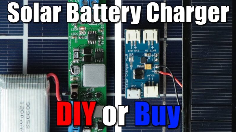
They were produced in 24 hours and shipped to Germany in only three days So feel free to give JLCPCB a shot by uploading your gerber files today First off, let's take a closer look at the Buy option At first sight, the board quality, as well as all the solder joints seem pretty decent The only thing I subjectively disliked were the JST connectors But thankfully the board offers breakout points for the solar and battery connections The main IC of the board is the CN3065 constant current/constant voltage linear charger for single cell lithium ion and lithium polymer batteries Say that three times fast After inspecting its pin description, as well as its detailed description in the data sheets It seemed like a suitable choice for small solar panels that deliver 4.4 volts to 6 volts Thankfully I got such solar panels laying around Like this 110 by 60 millimeter one that can do 6 volts and up to 1 watts.
So So for testing purposes, I directly connected the solar panel to the PCB through two thin wires and As you can see by shining light on the panel, the solar charger does react to it, which was a good sign next it was time to find a test battery which ultimately turned out to be a 1200 milliamp-hour Lipo battery But right before I was done soldering it to the PCB I realized that the solar charger IC here only features an over-voltage protection during charging But misses and over-discharge protection and more importantly a short-circuit protection This is especially important since the battery voltage is simply bridged over to the SYS OUT JST connector Which means we could easily short the battery here if we make a mistake So to protect the Lipo for now, I added an additional protection circuit to it before hooking it up to the solar charger At this point I wanted to test the circuit setup outside but surprise it is December and the sun did not feel like working with me As an alternative I had to create my own sun with an LED panel After attaching the solar panel to its with duct tape and cranking up the brightness The charge LED turned on and the battery started charging move around to 27.5 milliamps After then measuring the input current at the solar panel side as well as its voltage and the battery charge voltage I came to the conclusion that I was dealing with an efficiency of around 70% at the time Since this circuit works in a linear fashion and does not utilize MPPT for the solar cell, that is definitely acceptable and Because the circuit had no problem reactivating the charging while the solar radiation strength was oscillating a bit I have to say that the circuit is definitely usable for small projects But then again it got not sufficient protection features for the battery No boost converter to create stable 5V for your projects and no MPPT feature for the solar panel So naturally, those were the goals for my DIY solution Which is why I visited the website of Consonance Electronics next Which are in fact the manufacturers of the CN3065 IC There I found out that they got a whole section with solar panel powered charger IC's After comparing all of those, I decided on the CN3791 Which works with a single cell as well But uses a switching technique which should guarantee a higher efficiency at higher input voltages Works with up to 28 volts solar panels charges with up to four amps and features MPPT functionality Along side its other features which were mentioned in the data sheets.
It seemed like a perfect fit and Luckily, the IC was also easily available So I used the typical applications circuit of the data sheet as a reference to create my own schematic with the Easy EDA software The datasheet also provided guidelines for the capacitor selection as well as the inductor, MOSFETs and diode selection Which was certainly helpful while creating the schematic the only thing which I was uncertain about at this point were the resistors R8 and R9 Which are used for setting the MPPT voltage but more about that later Once the solar charge IC schematic part was complete I simply opened up my old Lipo charge protect boost project and added the protect/ boost components to my new Solar Charger schematic and Through this simple addition.

I added an overcharge over-discharge and over current protection as well as a 5 volt boosted output Which means that all my goals for my DIY solution were fulfilled Next I clicked the convert to PCB button and started arranging all the components in a logical and functional order After then creating all the traces and turning the top and bottom layer into a ground top layer The boards did not look half bad So I exported the gerber files of it and then ordered the boards for pretty cheap Just like I mentioned it earlier from JLCPCB Alongside, I also ordered all the mandatory components for the board and after waiting for a few days I was not only greeted with a ton of components but also the PCBs which made a good first impression under the microscope That means it was time to solder the teeny-tiny components to the PCB For which I mainly utilized a soldering iron with a very fine tip as well as a bit of additional flux and solder The whole process took me around 2 hours and to my own surprise did not turn out that badly this time At least in my opinion Anyway, after soldering all the SMD components I added the through-hole components and just like that My DIY solution was complete, but did it work? To find that out.
I firstly hooked up my lipo battery this time though without the protection circuits and After flipping the power switch the output of the board delivered 5.13 volts. Perfect. Through the help of the USB constant loads and my lab bench power supply, I then calculated the efficiency of the boost converter which turned out to be at a maximum of 81 percent and features a maximum current draw of eight hundred and seventy milliamps Afterwards, I also tested all the protection features which worked just fine Now for the solar panel tests, I did not feel like working with such a tiny panel instead I went with this 10 watt one, which features a maximum voltage of 21 volts, a maximum current of 0.61 amps and an MPPT voltage of 18 volts This voltage is important for our DIY board Since the MPPT pin of the IC needs to be at a voltage of 1.205 volts when those 18 volts are applied to the resistor network So after a bit of calculating I got the required resistor values and thus soldered them in place on the PCB Once that was done.
I hooked up my solar panel to the boards and positioned it very professionally next to my LED panel After cranking up the brightness to the maximum. The circuits came to life and charged up the battery successfully and Yes, you can charge it while outputting a constant 5 volts for your projects but after measuring the input power /output power, it seemed like the efficiency of the circuits was still a bit lacking to say the least As a result, I went outside in order to find some proper sunlight while monitoring a couple of important values But no matter how much I tried I never got any decent results due to inconsistent solar radiation But what I can say from the outdoor test, is that the MPPT tracking seems to function correctly even though the set voltage seems to be a bit higher and Luckily, I was able to perform a successful indoor efficiency test later on which turned out to be around 62 percent which was acceptable considering the terrible experiment conditions So all in all I'm pretty happy with my DIY solution Since it adds all the important missing functions of the commercial products While still being versatile due to its wide voltage input range The only negative things are they spent time for soldering and the money aspects? But for me that is definitely worth it, which is why DIY is this time the winner But what do you think? Let me know in the comment section below As always, thanks for watching.
Don't forget to Like, share, subscribe Stay creative, and I will see you next time!.
As an Amazon Associate I earn from qualifying purchases.