

As an Amazon Associate I earn from qualifying purchases.

hello everyone my name is Lucia welcome
to the second part of the skids steer build I've already made technological openings
in the oil and fuel tanks for filters refueling and fuel level sensor and now
it's time for the next step with a lot of connections that I have to put together
precisely so let's not waste time and start friends to be honest so far the front part of
the boom arm seems to be the hardest for me because it contains several main connections
that affect a lot of characteristics also I'm not an engineer and I feel lack of technical
knowledge and CAD design skill so I can't design the project in advance because I don't have the
whole picture in my mind and by the way all the machines CAD programs and controllers are useless
without this computer and mine needs to see first that's why I constructed this installation it
gave me some answers on my questions but there are still a few left pictures from the internet
are not too informative so I decided to use a method that I tested while building my CNC plasma
cutter it's called find in your city look at the advantages of the construction and then adapt
them to your project yesterday I spent almost the whole day driving around my city in search
of a suitable model of a skid steer that I could find in the streets and I found one looked
at and so it's time for making my own design okay these pipes these ones are parallel this
one is horizontal so now I can fixate them it's very important because these connections will
consist of several plates in different planes and both connections should be totally identical
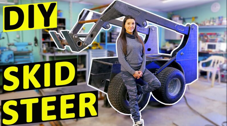
in order for the lift arm to work properly well now it's already not a washtub with wheels
but finally the shape of the loader started to define lift arms build might seem easy for you
but it was a real test of perseverance for me with all that measuring calculating thinking
of configuration creating several options of the design choosing changing and redoing it for
several times then building two lift arms so that all the holes were coaxial and so on and thinking
over and designing the drawings took even more time and efforts than building according to ready
plans but so far I do like how the result looks however there was some annoying mistake on my part you have probably noticed that lift arms look kind of unfinished the reason is that a plate that
repeats the contour of adjacent parts was supposed to be here until I realized that I haven't
considered a hydraulic cylinder for this assembly I mean I put it here while making the installation
that I showed you earlier in this video but this pipe hasn't yet been sawn off and I
assumed that I would shorten the hydraulic cylinder rod by six centimeters and it seemed to fit in
there well my mind was blown by thinking about the articulation of all these plates at that moment
and I just forgot about the exact calculation of the hydraulic cylinder insert simply forgot
and now when lift arms are almost ready I understand that even if I shorten the cylinder
rod its upper hole will be located here where I have nothing to attach it to in general I had
plenty of emotions and all of them were obscene then I went through all the stages of acceptance
and finally realized that a solution does exist in any case I just need to think it over thoroughly
either way I get comments that say you guys are waiting for part two so I decided to
leave that solution for the next video if you like this video please like
and subscribe to my channel for more videos also please feel free to write in the
comments whether you like my design or not because I need an outside perspective okay
that's it see you in the next video bye bye

As an Amazon Associate I earn from qualifying purchases.