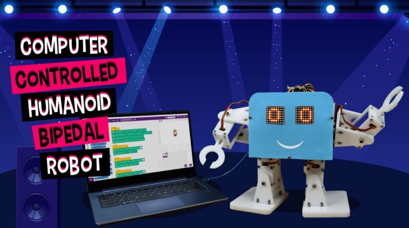
Hey there, Among all robots, humanoid robots take centre stage. And they are the cutest when they dance and
have expressive eyes! In this video, we will show you how to build
a humanoid robot from scratch, make its connections, calibrate it, and finally program it to control it using the keys of a keyboard. Before we start building the robot, let’s first set the angles of all the servo motors that we’re going to use to 90 degrees. First, connect the metal servo to Servo Channel 1. From the menu, select Controls, then servos, then Servo 1. Now, using the potentiometer, set the servo angle to 90°. Similarly, set the servo angle of the remaining 7 servos too. Now, let’s get on with the assembly. Take the body base plate and attach two metal
servos in the spaces given using M4 bolts. We will be making our entire robot on the base. Once done with fastening the servos, take the leg servo horn plate and attach
the two-sided servo horn to it using servo screws. Repeat this for the other leg. Now, attach both leg servo horn plates to the body base plate by attaching the servo horns
to the servo heads using servo bolts.
Now, let’s assemble the legs. Take the leg back servo plate and attach a
metal servo to it using M4 nuts and bolts. Next, attach the leg side plates to the leg back servo plate using M3 bolts of length 12mm and M3 nuts. Then, take the leg bottom plate and attach it to the
leg side plates using M3 bolts and nuts. Repeat the same process for the other leg. Then, take the leg front plate and screw
M4 bolt and nuts to it in the hole given in the centre. Now, fix this leg front plate to the leg side plates
using M3 bolts and nuts. Make sure that the slot given for the wire
to pass is close to the body base plate. Next, attach the leg bottom plate to the leg front and backplate using M3 bolts and M3 nuts. Repeat the same process for the other side too. Once the leg sub-assemblies are ready, fix them to the leg servo horn plate by attaching the servo horn to the servo head using servo bolts.
With this, the leg assembly is complete. Next, let’s begin with the feet assembly. Take the foot base and glue it to the foot sole. Then, take the foot servo horn plate and attach
a two-sided servo horn to it using servo screws. Next, place the foot servo horn plate on the
foot base and fasten it using M3 bolts and nuts. Now, let’s attach the feet assemblies to the leg assembly by attaching the servo horn to the servo heads using servo bolts. Then, attach the foot front plate to the leg assembly
using M4 bolts and M4 locknuts.
This will give movement to the feet of the robot. The lower body of our humanoid is complete. It’s time to build the upper body. Let’s start with the shoulders. Take the body side plates and attach the metal
servo to it using M4 bolts of 15mm and M4 nuts. Once done, attach that body side plate to
the body base plate using M3 bolts and M3 nuts. Make sure that the servo head points outwards. Now, take the shoulder servo horn plate and attach
a double-sided servo horn to it using a servo screw.
Finally, attach the servo horn of the shoulder servo horn plate to the servo head on the body side plate using a servo bolt. This allows the movement of the entire hands of the robot. Now, let’s move on to the assembly of the arm. First, take the arm back servo plate and attach
the servo to it using M4 bolts and nuts. Then, attach the arm bottom plate to the arm back servo plate
using M3 bolts of 12mm length and M3 nuts. Screw M4 bolt and M4 nut into the hole given
in the middle of the arm front plate.
Next, attach the arm front plate. Take the arm top plate and screw
the claw on it using M3 bolts and nuts. Fix the arm top plate to the arm front and
backplate using M3 bolts of 12mm and M3 nuts. Next, take the shoulder backplate and attach
the servo horn to it using a servo screw. Attach the servo horn fixed on the shoulder
backplate to the shoulder servo horn plate. Next, fix the arm assembly by attaching the
servo horn to the servo head using a servo bolt.
Make sure the arm is straight. Next, attach the shoulder front plate. Similarly, complete the second arm. Attach the body front plate to the
body base plate and the side plates using M3 bolts of 12mm length and M3 nuts. This will act as the base for the face of the robot. Now, let’s assemble the Back. Bring out the servo wires to the top by
passing them through the slots given. Attach the body backplate to the body base plate and the side plates using M3 bolts of 12mm length and nuts.
Now, we need to make the eyes of the robot. We’ll be using two 8 * 8 LED matrices for the same. Insert the 8*8 LED matrices into the space given on the front plate. Insert them in such a way that CLK(clock) pin is on top. Now, let’s make our humanoid robot look attractive. Take the print out of the face and cut out its face and eyes. Then, stick it on the body front plate using a glue stick. Next up: connections. First, extend all the servo wires by using male-to-male jumper cables. Next, take a two-cell battery and place it inside the hollow space.

Now time to bring evive into the picture. Take two 55mm male-to-female standoffs and
attach them to evive. Then, fasten evive using M3 bolts of 12mm length. Now, connect both the LED matrices to evive: Let’s first connect the Left Dot Matrix: Connect CS(Chipset) to Digital Pin 10 of evive. Connect CLK(Clock) to Digital Pin 11 of evive. Connect DIN(Data Input) to Digital Pin 12. Connect VCC to +5V of evive. And connect GND to GND of evive. Now, let’s connect the Right Dot Matrix: Connect CS(Chipset) to Digital Pin 23 of evive. Connect CLK(Clock) to Digital Pin 22 of evive. Connect DIN(Data Input) to Digital Pin 24 of evive. Connect VCC to +5V of evive.
And connect GND to GND of evive. Now, let’s connect the Servos. Connect evive’s VVR to the breadboard using
Male-to-Female jumper cables. Connect the VCC of all servos to the VVR voltage line. Then, connect the GND of all servos to the
GND line on the breadboard. Finally, connect the signal of all the servos to evive. Finally, connect the battery to evive’s VIN terminal. Now that the connections are done, it’s
time to calibrate our robot. We are going to calibrate it using PictoBlox. Open PictoBlox. To work with the robot, we need to add the humanoid extension. As we need to work with a humanoid robot in stage mode, we must first upload the stage mode firmware to it.
Drag and drop the when evive starts up hat block and upload stage mode firmware block into the scripting area. Then, upload the script by switching to the upload mode. Now that the firmware has been uploaded successfully, let’s create the script for calibration. First, drag and drop the when flag clicked hat block. Next, drag and drop the
Connect left leg () right leg () left foot () right foot() block.
It will define the PWM pins to which each
of the legs and the feet servos are connected. Next, drag and drop the
Calibrate left leg () right leg () left foot () right foot () block for calibrating the angles of the servo motors of the legs and feet and save them in evive’s memory. Now, drag and drop the Connect left shoulder () right shoulder () left hand () right hand() block. It will define the PWM pins to which each of the shoulder
and the hand servos are connected. Then, drag and drop the Calibrate left shoulder ()
right shoulder () left hand () right hand () block for calibrating the angles of the servo motors
of shoulders and hands and again saving them in evive’s memory. Click on the green flag to run the script. Make sure all the arms are straight and the feet are facing forward.
If not, fix the errors by changing the values
accordingly in the calibration block. Once the humanoid robot is calibrated, we’ll write a script to control it using the keys of the keyboard. Now, every time we click the green flag, the robot should always return to its calibrated position. Thus, first, define the PWM pins for all the
servos and then calibrate all of them. Finally, initialize the 8 * 8 matrices and define their pins too. Following are the controls for the humanoid robot: When up arrow key is pressed: the robot should
move forward and should have circular eyes. When down arrow key is pressed: the robot
should move backward with hearts as his eyes.
When the right arrow key is pressed:
it should turn right with normal eyes. When the left arrow key is pressed:
it should turn left with the cross in his eyes. On pressing w, his hands should go up. On pressing s, the hands should come back down to the default position. On pressing a, the robot should do a Hi-Five
with wicked eyes. And on pressing d, it should do a handshake
with circular eyes.
With this, the code is ready! Click on the green flag to run the script. Enjoy! That's it for this video! If you liked it, give it a thump up! And share it with your friends. If you have any ideas, doubts, or suggestions, let us know in the comment section below. Before we part ways, we have some exciting news to share! We are now a family of 1K! 🙂 Thank you so much for all the love and
for becoming a part of our STEM club.
We’ll see you in another video. Till then, happy tinkering! Bubye!.
As an Amazon Associate I earn from qualifying purchases.


