

As an Amazon Associate I earn from qualifying purchases.

in video number 321 we looked at dc current sensors today we will look at how to measure ac mains currents which is much more difficult and more dangerous because it can kill you if you do not pay attention and because measuring ac power is useful in our homes we will also look at how to measure voltage and calculate power to measure correctly we have to learn about phase shifts and power factor and i will tell you the essential rule to live long around high voltages crazy youtubers here is the guy with the swiss accent with a new episode and fresh ideas around sensors and microcontrollers remember if you subscribe you will always sit in the first row in today's video we will understand the difference between measuring dc and ac look at ways to measure 110 or 230 volt without electrocuting our devices look at the different definitions of voltage current and power and where they are useful discover the devastating effects of a simple dimmer discover how difficult it is to get an accurate measurement especially with our microprocessors discover the importance of phase shift and power factor look at a few sensors and devices and find out which are good and which are not so good but before we start i tell you the most important rule for working with mains voltage always keep one hand in your pocket always otherwise you can die young because if you touch electricity with one hand in your pocket the current flows towards earth through where you sit or stand and this is usually an insulated connection so the current is small enough to send you a clear message called electric shock but not to kill you if you touch the two wires with both hands insulation is much smaller and current flows directly across your heart where it does its thing to kill you now you are informed and we can start with the topic but wait we also need a rule to protect our most valuable instrument the oscilloscope because bench oscilloscopes are grounded i never use mine in conjunction with mains it is too easy to create problems that at least kill a fuse or even worse kill my oscilloscope i always use my battery operated oscilloscope for that now we are ready to proceed in the 1880s edison and tesla battled over what is the better concept alternating current or direct current the result of the battle was that we use ac for power distribution and dc to power our gadgets why do we have to bother because they have different properties two differences are essential for this video the first with ac it is easy to transform voltages up and down using a simple transformer this was particularly important for the decision to use ac for power distribution back then the second one it is much easier to measure dc voltage current or power why is that dc usually is more or less constant at least over a short time ac voltage changes all the time and with it also the current this creates a problem what is the voltage if it always changes a problem which will occupy us later for some time as said before ac easily can be transformed from one level to another according to this label this transformer should produce 15 volts on the secondary if we connect it to 230 volts on the primary coil both coils are entirely insulated so we do not touch mains if we only work on the secondary very important because now we can work with both hands in this video we will use transformers to avoid any casualties when we connect it to mains and connect our oscilloscope to the insulated secondary site we see a sine wave with an ever-changing voltage it even gets negative 50 percent of its time who can say that this is 15 volts for me it looks like the bad swiss joke where we say that even a broken watch shows the exact time two times a day the voltage is also 15 volts from time to time but its peak voltages are far away from 15 volts the oscilloscope shows a peak to peak voltage of around 60 volts crazy let's check if my bench multimeter provides a better result it shows roughly 20 volts and this old multimeter agrees with the benchmeter two to one so the oscilloscope must be wrong like in real life the wife has a different opinion from mine also two to one and she is right so the winding ratio between the primary and the secondary is about 10 to 1.
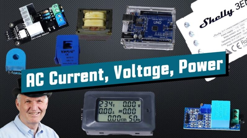
By the way if we choose dc on the multimeter it only shows a tiny amount because the positive and the negative parts are cancelled out how can we deal with this situation one approach is to look at power it is measured in watts which is volts times amperes so how much power is in ac we multiply volts times ampere at each point of the curve and get this power curve it is always positive if we want the dc equivalence we have to calculate the area below the curves which is simple in the case of a sine wave we fold the negative parts and multiply peak volts and amperes with 0.7071 the power then is automatically 0.5 times the peak power which is visible in the diagram the area below the power curve is smaller than the one below the voltage the dc equivalent of ac is called root mean square or rms so a multimeter should be able to calculate the area below the curve in real time not all multimeters can do it this old one for example does not have this feature as a compromise it assumes the curve is a sine measures the peak and does the multiplication that is why it's only usable for sine waves by the way the oscilloscope also has such a rms function and the result is comparable with the multimeters but it is not the 15 volts from the datasheet why if we connected a load to the secondary the voltage would drop its specification is made with a current of 0.3 ampere the current on the primary is about 10 times smaller than on the secondary why because the power on the primary and on the secondary should be the same we can use this effect in the next chapter to measure current let's summarize the theory before we go on with the measurements if we want to compare the power of ac with dc we have to calculate the areas below the ac curves and so calculate the rms values 110 or 230 volts ac in power distribution therefore means 110 or 230 volts rms 110 volts rms means 156 volts peak voltage and 312 volts peak to peak so which voltage is relevant for driving a motor or heating rms voltage is right if you want to calculate the maximum voltage of capacitors or other electronic parts the peak to peak voltage is essential maybe you ask yourself is this all necessary unfortunately yes as we will later see now we can plunge into practical matters as a first introduction we could try to detect mains voltage with our microcontroller we could use a voltage divider a diode and a capacitor to reduce the voltage to 3.3 or 5 volts dc but this is not what i recommend because it offers no insulation too dangerous if you try to do something like that at least use three resistors in series if one has a problem you still are a little bit protected and small resistors are also not specified for 300 volts peak peak here i have a better solution a simple device that contains a opto-coupler and a few other parts it works with 3.3 and 5 volts and signals a microcontroller if mains voltage is present big clive would probably not be excited about the distance between ac and dc but i can live with it another possibility is this hcpl 8700 optocoupler with a built-in bridge rectifier it can detect ac and dc voltages and signal it to your mcu what if we want to measure voltage more accurately then we have to use a board like this one this blue set mpt-101b is a small transformer in addition they added an operational amplifier with a variable gain as well as two bias resistors to avoid negative voltages if we connect it to mains we get a sine wave which we have to adjust to maximal linearity now we have a positive signal which can be read by the adc of an mcu fortunately i found a library which does exactly that its example sketch loops every millisecond so an arduino is more or less busy with measuring and calculate results but is it any good to challenge this setup we do not use a nice sine wave everybody can do sine waves no we do something hard like this unimposing bulb which is dimmed as we see such dimmers cut areas out of the sine wave to reduce power the result is a horrible looking signal as we see here of course it might also be influenced a little by the transformer and the op-amp but can the arduino calculate the proper rms voltage not in its initial setup with a very short measuring period the value jumps quite a lot but if we implement a moving average the value measured by the arduino is more stable and comparable with a bench multimeter not bad arduino the old non-rms meter by the way shows an entirely different value which is what we expected so we know how to measure rms voltage next is measuring current in video number 321 we used hole sensors to measure dc currents they also can be used to measure ac currents this is why we do not cover it again they also insulate mains from our valuable mcu and reduce voltage today we will use a different way which is very similar to the way we measured voltages we use transformers not transformers like this one or this one transformers like this sct-013 if we open it we see two things an iron core and a coil this coil is the secondary winding which will be connected to the mcu by this cable but where is the primary winding it uses the same principle as this clamp meter the primary winding is only a wire as before the current is transformed with the ratio of the windings the marking here says 1 volt per 10 ampere this sct-013 is not for small currents fortunately we also get smaller transformers like this set mct 103 it creates 5 volts for 10 amperes but it has no split core and you have to remove the cable to mount it by the way if you feed the wire two or more times through the core the secondary voltage is increased useful for measuring smaller currents the output of these transformers is also an ac voltage and we have to pay attention if we attach the core around both wires the resulting current is zero we have to mount it around one wire only connect a 50 ohm resistors across the two pins and attach it to the oscilloscope now we see a similar curve as before with the voltage this is no surprise because a wall frame bulb is a pure resistor with a linear correlation between voltage and current so the same software can be used to measure and calculate currents it just has to be calibrated differently so we would need a secondary arduino for measuring the current maybe not the best idea fortunately chip designers created chips to do all the heavy lifting for us and manufacturers created ports and devices which use those chips one well-known board is this one the pcm004 it uses this quite large sd-3004 chip to measure current and voltage and to calculate power and the power factor it can do the rms calculation and even has a real-time clock to measure used energy which is of course power times time we even get an arduino library but unfortunately i was not able to get it running i have a version 1 and now they sell a version 3.

Maybe the protocol changed from version 1 and the libraries do no more support my board anyway we can learn how to wire those devices the voltage transformer is connected across mains voltage and the current transformer is attached to one of the wires of the load by the way they now sell version 3 in a transparent case to protect you from shocks to play around and understand what happens this is maybe a solution for you but there is a more attractive solution the sonoff pow i already covered it in video number 99 as all sonoffs it contains a switch for power measurements it uses an hlw at12 chip which contains two adcs for voltage and current as well as algorithm to calculate rms values as we see it has no current and no voltage transformers to save money interesting so pay extreme attention the whole board is attached to mains and must not be touched the case and the wi-fi connection to the insulation they now sell a r2 version which uses a cse 7766 chip it should be more accurate as this version there is another similar device like the sonoff pow the shelley em which uses the ade 7880 manufactured by analog devices it can accurately measure one voltage and two different currents the chip can do more as we will later see because it uses transformers it has a high current rating of 50 or even 120 ampere it has no switch built in so i assume it is made for mounting in the fuse box and the sonoff is made to be connected to specific devices where you want to get the power consumption but these two current transformers force us to deal with the final topic phase shift to show you what i mean with phase shift i feed a capacitor and a resistor in series with a sine wave from a signal generator yellow is the voltage across the resistor which is proportional to the current in purple you see the voltage across the capacitor it is lacking the current this is what we call phase shift by the way if i replace the capacitor with an inductor the voltage leads current a negative phase shift why is this important as we saw before power and energy are the areas below both curves if voltage and current have a phase shift of 90 degrees for example the power curve is no more on the positive side it oscillates around the x-axis and on average is zero if you think this phenomenon is rare you are wrong motors for example are substantial inductive loads and they shift phases a lot we can draw this simple triangle here we have the total or apparent power we can divide it into two parts real power is the part which is converted into mechanical power or heat and reactive power is just shifted in and out the relation between the reactive and the real power is called power factor do you remember this chart at 90 degrees phase shift total power adds up to zero ideal capacitors and inductors shift the phase between voltage and current by 90 degrees this is why they do not get hot reactive power by the way usually is free of charge for households because as we saw before the energy company gets it back so you see why we had to have this discussion if we go on we discover another phase shift i'm no specialist in power distribution but i try my best i start with what i know here in europe we have a three-phase system all households get three phases called l1 l2 and l3 plus a neutral delivered to their homes each phase delivers around 230 volts rms as we have seen before but their phase is different by 120 degrees the voltage of l2 is 66 milliseconds behind l1 and l3 is 66 milliseconds behind l2 each 230 volts power outlet is only fed with one phase plus the neutral wire the third hole is protective earth which will not be covered here if we look at a regular power outlet we only see a sine wave as we experienced before only if we use a different outlet providing all three phases we see the difference the voltage between two phases is 400 volts instead of 230 volts so we can transport higher power with the same wire diameters such outlets are usually used to connect washing machines with motors and energy hungry heaters in the u.s it seems to be different they only have two phases of 120 volts these phases are 180 degrees out of phase and therefore you get 240 volts between them this concept is called split phase why are those facts important if you measured the voltage at one phase and current at another your values would be bluntly wrong if i enter 120 degrees phase shift the power curve is mainly below zero and your meter will show mostly reactive power you would be surprised about the unexpected high invoice of your energy provider so pay attention that you always measure voltage and current for the same phase this is no problem for the sonoff because it only has connectors for one phase but the shelley em can only measure one voltage plus two currents there it is imperative that you only measure loads that are attached to the same phase if you want more you have to upgrade to the shelley 3em it uses the same ade 7880 chips as the em but measures voltage and currents on all three phases with such a device you can measure the total energy consumption of your house either in the u.s or in europe if you do not need a connected device such self-contained power meters can be another possibility this one even displays the power factor this was quite a journey summarized ac has a significant advantage that we can use simple transformers to change voltage and current levels but dealing with ac is much more complex because of its fluctuating nature we used transformers to step down mains voltage and step up currents to get a decent voltage for our adcs we did not cover whole sensors for ac current measurements they were covered in video number 321 because voltage and current changes at a frequency of 50 or 60 hertz we have to measure many times to calculate the correct values in addition ac voltage and current usually are not in phase therefore we have to consider this fact to measure real as well as reactive power we saw that a simple dimmer could screw things up even further and make it very complicated if we deal with ac we have to pay attention that our instruments are correctly calculating the rms value i'm sure there are differences in how well they do that but this is stuff for another channel an arduino together with a cmpt101 can do the job but needs nearly all its power for just doing that this is why it is advisable to use specialized chips for that purpose we looked at the different devices available on the market like the pc em-1 the sonoff pow the shelley em and three em and a standalone meter in europe we use a three-phase system in the us they only have two phases in households if you do not measure voltage and current at the same phase you will get completely wrong measurements one last thing if you think only motors have a bad power factor look at what happens with this simple dimmer the bulb has as expected a power factor of 1 at full throttle if we dim it the power factor gets worse and worse even with a resistive load if we multiply the indicated volt with ampere we get a much higher voltage than the resistive power displayed by the meter this value by the way is called walt ampere not watts cool little instrument for just 10 dollars as always you find the relevant links in the description i hope this video was useful or at least interesting for you if true please consider supporting the channel to secure its future existence thank you bye
As an Amazon Associate I earn from qualifying purchases.